Jaha! The buffer shown earlier in this thread is just a beefed up version of the one shown in your link at the bottom of the page.
Youre getting the idea, use that buffer and replace the BJTs in the JLH, and what do you have ........
Not that is any better performance wise, except higher input impedance and the thrill of saying its very different or I discovered it just because you havent seen it before.
Btw, the last circuit can be used to make an excellent performance buffer that can even drive low impedance loads.
Last edited:
OK, if we're playing around with headphone amps, I really don't see a need for more than 6dB of gain. Unity gain would be fine actually. This one has 2.7x10^-5% (0.000027%) distortion @1kHz, 990mVrms into 30 ohms with 6dB of gain. It's nothing fancy. DC offset on the output is less than 1mV (730uv). Bandwidth shows a very mild bump @ 10MHz. No biggie in my opinion.
Boy, its like pulling teeth here.... I am into optimizing a given circuit topology right now.... like in LA..... can you redo this one without C1 and C3 and still have no drift and offset issues (at 12db gain)? Thx - RNM
Last edited:
Boy, its like pulling teeth here.... I am into optimizing a given circuit topology right now.... like in LA..... can you redo this one without C1 and C3 and still have no drift and offset issues (at 12db gain)? Thx - RNM
Some of us are into optimizing a circuit, some of us want to argue about the meaning of "maybe not" and others just want to do other things I guess. It's no problem.
For that circuit, to eliminate the input coupling cap would require going to jfet inputs with gates referenced to ground I think. To eliminate the cap in the feedback loop would increase the DC offset on the output. I didn't know these were your goals, sorry! I just threw it out as an example of what's possible, not that it's better than your circuit or anything. I'm sure yours is super good since you have far more experience than I do at this.
This is in the spirit of "look what I did!", and not anything like "I'm better than you" or something like that.
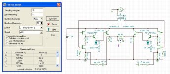
I was fooling around with SRPP follower bridge circuits and did this one. I think it's pretty cool. Eight transistors if you don't count the CRD. The only downside I can see is the need for a really big capacitor in the feedback circuit and monster heatsinks on the outputs. Bandwidth and phase response are really nice according to the simulation in Tina. If I didn't have to drive 30 ohms I could get away with 6 transistors. Dang, pretty cool I think.
Output is 990mV rms into 30 ohms @ 1kHz. Distortion is very low, as you can see.
Attachments
Using "may not" makes the reader think the writer sees the subject as pessimestic.
Not this reader. I saw it as simply cautionary. And NO proper construction of that sentence would have had it as meaning ALWAYS as you attempted to construe it. Either you need to work on your English comprehension, or you were being intentionally disingenuous.
se
Youre getting the idea, use that buffer and replace the BJTs in the JLH, and what do you have ........
Not that is any better performance wise, except higher input impedance and the thrill of saying its very different or I discovered it just because you havent seen it before.
Btw, the last circuit can be used to make an excellent performance buffer that can even drive low impedance loads.
The article doesn't really explain the circuit very well as far as I could see. As I understand it, the input is a pair of complimentary jfets arranged as source followers driving complimentary BJT's in common emitter configuration with 100% feedback, but I could be completely wrong and it wouldn't be the first time.
Not this reader. I saw it as simply cautionary. And NO proper construction of that sentence would have had it as meaning ALWAYS as you attempted to construe it. Either you need to work on your English comprehension, or you were being intentionally disingenuous.
se
I saw it the same way as homemodder, so his English is just fine.
"Different" is not synonymous with "Better."
I just wanted to say that this was my interpretation of the quote as well.
I thought sharing how to make a circuit topology perform to its best potential was a lot of what this site was all about. Am I in the wrong place?
No, not at all, but with 200k+ members, you have to learn to ignore the noise.
Gee, and I look at what was originally presented and I see a nice polished circuit following what I perceive as the current state of the art design trend. That is to properly balance the components to get a circuit that performs very well. Some are going to more difficult to obtain parts others selection, to reach these goals.
I guess that is due to my inexperience. I have been at audio full time for only 40 years.
Once Jan gets around to sending me my copy I may have more insights.
I guess that is due to my inexperience. I have been at audio full time for only 40 years.
Once Jan gets around to sending me my copy I may have more insights.
Gee, and I look at what was originally presented and I see a nice polished circuit following what I perceive as the current state of the art design trend. That is to properly balance the components to get a circuit that performs very well. Some are going to more difficult to obtain parts others selection, to reach these goals.
I guess that is due to my inexperience. I have been at audio full time for only 40 years.
Once Jan gets around to sending me my copy I may have more insights.
Not to anyone in particular: There seems to be a lot of assumptions - based upon what, I dont know. This is an optimization of existing circuits put together and selected for best results. I hope to get to the not so obvoius parts when everyone reads the article. Sorry but I just can not rewrite the artcle here. Lets take an easy one but I think more intersting question for you ---- anyone care to guess why thier favorite topology or design isnt thermally stable and this one is? The transistors were not mounted to a common heat sink nor the bias circuit attached to the transistor cases. On your mark! ready. set. Go!
Last edited:
What does 'thermally stable' mean? That the output offset remains relatively constant irregardless of temperature?
Also that the bias doesnt drift much with temperature.
Not to anyone in particular: ....Sorry but I just can not rewrite the artcle here. Lets take an easy one but I think more intersting question for you ---- anyone care to guess why thier favorite topology or design isnt thermally stable and this one is? The transistors were not mounted to a common heat sink nor the bias circuit attached to the transistor cases. On your mark! ready. set. Go!
Actually I have been doing a bit showing that thermal mistracking can result in distortions that may be missed by some measurements.
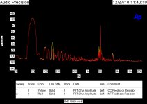
Attached are things I have shown before. A distortion comparison of a carbon composition resistor compared to a metal film type of the same value, tolerance and wattage. With a THD measurement they are very close. With an IM measurement at 50Hz and 2 KHz they show differences. That is because the 50Hz is doing more cyclical heating of the resistors.
Attachments
Actually I have been doing a bit showing that thermal mistracking can result in distortions that may be missed by some measurements.
Attached are things I have shown before. A distortion comparison of a carbon composition resistor compared to a metal film type of the same value, tolerance and wattage. With a THD measurement they are very close. With an IM measurement at 50Hz and 2 KHz they show differences. That is because the 50Hz is doing more cyclical heating of the resistors.
With a THD measurement at 50Hz they are not close. You don't even need to perform the IM test the thirds on the 50Hz in the left plot can be used to compute the IM sidebands on the second frequency. It is not an accurate blanket statement that "there are things that show up in an IM test that don't in a THD test". This relates to what you asked yesterday.
You need to be more careful in stating all the conditions.
As I mentioned long ago the phase of the sidebands could probably be used to separate the thermal from voltage effects.
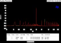
EDIT - On second thought the thirds in the second plot don't look very close at all.
Last edited:
Scott,
Yes, I forgot to mention what we are looking at is the distortion of the same amplifier with the only difference being the feedback resistors.
The sidebands are not exactly what I expected from just the THD plots. In addition to the distortion difference in the two plots the amplifier also behaves a small bit differently. (As you can see the "noise" level has shifted!) So this is not a true resistor vs resistor comparison.
I usually use a much higher wattage resistor in the feedback than would seem necessary to prevent thermal issues but also to reduce the effects associated with its voltage coeffecient. Of course the metal caps at the end add distortion if they are ferrous metals. To make matters a wee bit more complicated, the materials used to dope the resistive material itself (eg metal film) can add distortion... doping to get tight tempco often uses material that is nonlinear. I wouldnt go so far as to make a blanket statment that all low tc resistors have higher thd. Just the materials used to alter the tc often are nonlinear.
Last edited:
I usually use a much higher wattage resistor in the feedback than would seem necessary to prevent thermal issues but also to reduce the effets associated with its voltage coeffecient. Of course the metal caps at the end add distortion if they are ferrous metals. To make matters a wee bit more complicated, the materials used to dope the resistive material itself (eg metal film) can add distortion... doping to get tight tempco often uses material that is nonlinear. I wouldnt go so far as to make a blanket statment that all low tc resistors have higher thd. Just the materials used to alter the tc often are nonlinear.
In LA #1 I show the distortion of various resistors and how I measured them. I have not shown there yet how to determine the thermo electric effects. I am not finding much of a voltage coefficient that is not explained by measurable processes.
That was a great article btw!! Thanks. Especially the sm types. Many of the best DAC have thd specs below the sm resistors! Anyway, I am thinking of power amps with voltage swings of up to +/- 80 volts... often across a high value 1/2w feedback resistor. Might need a high voltage or peak level test?In LA #1 I show the distortion of various resistors and how I measured them. I have not shown there yet how to determine the thermo electric effects. I am not finding much of a voltage coefficient that is not explained by measurable processes.
Last edited:
- Home
- Amplifiers
- Headphone Systems
- Marsh headphone amp from Linear Audio