I did actually try something along those lines. Used REW (Room Equalisation Wizard) as a software to pick out the peaks and dips to then resemble them using the Electri-Q plugin for Winamp. The effect was not as pleasing to me as dialling in a roughly biophonic curve using the same plugin. I also did notice that the dips and peaks used to vary by an octave or more depending on how and where I put the mic probe under the earpad (i.e. from the front or bottom, a little lower or higher, put it in some more or not as far, etc.), which made the whole affair a little awkward.
Did you do it exactly as I described because I didnt have that problem.... my HPhones were closed over the ear providing an air-tight seal. The tiny probe microphone should be placed at the ear canal entrance or even within the canal. But, the pressure was fairly constant anywhere within the small headphone-ear volume.
In fact, the test using this particular HP had been measured also with a professional dummy head system ($$$) and B&K probe mic. The results I got was nearly identical. Then I ran it thru an auto-EQ system (Audessey Pro) to flatten the response. This way flattens the headphone response as well as your particular ear shape affects.
I preferred the flattened response this way. The resonance of the ear canal can be dealt with same way if you are willing to insert the tiny probe into the ear canal. I am not sure that removing something like ear canal resonance is a good idea --- we dont hear that way. But flat to the entrance of the ear canal seems to work well and sound more natural/accurate to me.
THx-RNMarsh
Last edited:
The 2H and 3H are the only harmonics produced .... 4th and higher order harmonics are below the residual of the instrument. You ought to be able to get what I measured ---about -120dB re 1v --- with matched compliments every where.
With as few transistors as possible, these numbers compare well against high gnfb IC amp/opamp performance used for a headphone amp. But it is the sound which exceeded my expectations and hopes that it would be better than an IC amp.
Enjoy !
THx-RNMarsh
With as few transistors as possible, these numbers compare well against high gnfb IC amp/opamp performance used for a headphone amp. But it is the sound which exceeded my expectations and hopes that it would be better than an IC amp.
Enjoy !
THx-RNMarsh
Last edited:
Mr RNMarsh
Knowwing the importance of the zero tempoco of the input jfets
I have question what is the bias point of the input jfet pair ??
Is it an issue to consider different biassing points of the input jfet ??
I'm asking because if the bias level of the input jfet must be kept on the same level, there is limited range of Idss input pair , which can be used to get the right bias level , keeping in the same time zero tempoco point.
When biasing point is not an issue and we consider only zero tempoco point
we can get it with usage wider Idss range of the input jifets changing only value of the source resistors ?
But then we will get different biasing points of the input pair
keeping the zero tempoco point as a prinzip.
In short , the question is how important is the value of the source resistors of the jfet input pair for the preformace of the circuit ???
I saw someone recomended 2sk170GR / 2sj74 GR for the input pair.
According to my expirence there is no chance to get zero tempoco with usage ot of above device
Mr RNMarsh
I saw someone recomended 2sk170GR / 2sj74 GR for the input pair.
According to my expirence there is no chance to get zero tempoco with usage ot of above device
Good question -- You are correct. The choice of jfets included using a pair which could be operated at zero temp coeff. and also give good operation and low distortion without a lot of gnfb. The transistors chosen and their source resistor values assure this. Thus, no dc servo needed.
Thx - RNMarsh
I had bought an IC/opamp based headphone amp for about $450 via internet. It did not sound very good to me... a disappointment, in fact. That lead me to do my own circuit.
If you want to hear what a low global negative feedback circuit with wide open loop bandwidth sounds like, then this is for you.
If you want to use it to drive other gear directly (power amp etc HP amp using +/- 24vdc supplies) Here it is at 2v rms and at 8KHz... the THD is still -100dB.

THx-RNMarsh
If you want to hear what a low global negative feedback circuit with wide open loop bandwidth sounds like, then this is for you.
If you want to use it to drive other gear directly (power amp etc HP amp using +/- 24vdc supplies) Here it is at 2v rms and at 8KHz... the THD is still -100dB.
THx-RNMarsh
Last edited:
This Marsh amp is an incredibly good sounding headamp! Easily the best of many expensive commercial and DIY designs tried driving my LCD-3F cans.
It really should be GETTING MORE ATTENTION and folks DIYing it. It is something very special to these old ears. Thank you Dr Marsh for publishing your elegantly simple design. Its a gem.
I am now moving on from Audeze orthodynamics to Stax e-stats after building a KGST to power my SR-009s. Going to sell the LCD-3Fs but will keep this amp. It drove the flat impedance Audeze cans extraordinarily well.
A question now for Richard, how would his amp drive a reactive low impedance load? I have a pair of Altec Model 19s with a sensitivity of 102dB/1watt and 8 ohm nominal impedance. Can your amp (with or without mods) possibly drive those? In your article you touched a little on this issue. I only need a few watts, driving them with my 5 watt PP 6V6 amp ATM. Asking first before I try so I won't unknowingly destroy my Marsh amp.
Last edited:
Thank you and let me take another look and see if it could be made for use for driving the Model 19's.
Have the Stax changed/improved since company was sold?
-Richard
Thank you for looking into your elegant headphone driving the Model 19s. I love the Marsh amp, it pushes ALL my buttons in a good way. Ultimately, it highlighted that the LCD-3Fs were the bottleneck. I have a gut feeling the Marsh amp could also be excellent with the extremely efficient Altecs too, possibly displacing my preferred tube amp in that application too.
To answer your question, Stax is still Stax (so far) -a small company with traditional 1950s business practices in the 21st century.The products are still built in Japan and are of the same high quality. Edifier, the new Chinese owners have stated that will remain the case with Stax branded products, and will work on a lower priced line to be manufactured in China. Have to wait and see what the future brings on that.
There have been reports that the latest SR-009s have been revoiced to be a little less bright, but I have no expereince to verify. Mine sound very very good, but I am new to Stax so still in the honeymoon stage.
The KGST (a mini Blue Hawaii) amp is IMO a perfect amp for these e-stats.
kgst - Do It Yourself - www.Head-Case.org
Relatively inexpensive to DIY, and plays at a high level. For now my source is the limiting factor.
Last edited:
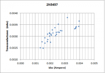
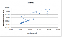
I tested a bunch more 2N5460 and 2N5457 -- this time I noted Vgs(off) and Idss and graphed the result. As you can see, the relationship is linear, but the variation is pretty significant. If you're matching these devices, it would seem best to measure both variables.
Attachments
But, why not adjust for lowest thd with the actual headphone plugged in instead of a resistor value? Sometimes, the complex Z of the real headphone (or speaker) is more difficult than a pure resistance and raised THd of the amp. If you have the equipment, you can use your own headphone when adjusting or balancing the amp
THx-RNMarsh
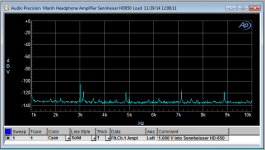
le voila -- il n'y pas de second harmonique:
Attachments
Could you do same with a -5458? I found more compl. pair matches per group (Idss) with this fet.
THx-RNMarsh
Sure -- what I've found is that the 2N5460's are about evenly distributed between 1.0 and 3.5mS while the 2N5457's are distributed between 2.4 and 3.9 mS.
It's easy to make a higher gm "2n5460" by paralleling 2 devices.
The Peak doesn't work particularly well with these low Idss devices. It tests JFETs between 3 and 5mA.
I tested a bunch more 2N5460 and 2N5457 -- this time I noted Vgs(off) and Idss and graphed the result. As you can see, the relationship is linear, but the variation is pretty significant. If you're matching these devices, it would seem best to measure both variables.
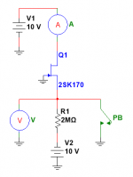
I'm trying to match some PF5102s:
http://www.mouser.com/ds/2/149/PF5102-99964.pdf
Will the circuit you posted also work for matching them by Idss, or can you suggest a circuit that would work?
Thanks...
I'm trying to match some PF5102s:
http://www.mouser.com/ds/2/149/PF5102-99964.pdf
Will the circuit you posted also work for matching them by Idss, or can you suggest a circuit that would work?
Thanks...
It should, the one thing to be watchful of is that the noise of some switching JFETs can be high.
I note with amusement that Fairchild semi has a new definition of a measurement parameter -- the umhous -- in Greek (ask Salas) I guess this would be the plural of umhos.
Dialed in -
Whoa ! Jack, you have really got that thing dialed in. What supply voltage are you using? Have you tried higher voltage?
And, are you using the original low C jFETs (2N5460 etal) or other?
THx-RNMarsh
le voila -- il n'y pas de second harmonique:
Whoa ! Jack, you have really got that thing dialed in.
What supply voltage are you using? Have you tried higher voltage? And, are you using the original low C jFETs (2N5460 etal) or other?
THx-RNMarsh
Last edited:
Whoa ! Jack, you have really got that thing dialed in.
Using a pair of 7AH 12V batteries and the Sennheiser HD650 cans.
Those are the 5457 and 5460 JFETs from Fairchild.
To tweak R10, I kept the original 249R in with a 200 ohm trimpot. These were paralleled with 820R which gives me a range of 191 to 290 ohms. The DC offset is plus or minus a millivolt or so.
So after a LONG delay, I'm finally going to put this amp together.
I recently got a pair of HD700's I want to try this amp with. I also have some orthos which I will also try it with.
I was wondering if the 2SD669AC and 2SB649AC output transistors are better, and if I should get a kit with those?
I don't mind paying a few extra $ for better sound.
Randy
I recently got a pair of HD700's I want to try this amp with. I also have some orthos which I will also try it with.
I was wondering if the 2SD669AC and 2SB649AC output transistors are better, and if I should get a kit with those?
I don't mind paying a few extra $ for better sound.
Randy
So and 2SB649AC output transistors are better, and if I should get a kit with those?
These are a bit faster than the OnSemi devices, hfe a little higher, higher voltage but less robust than the MJE200/210G...when I put together parts kits it was much easier to get 4 good matches with the 2S649/SD669s.
Matching the JFET's is a good idea, but I've also taken devices that were 1mS and 4mS apart and come up with THD which was still very low.
- Home
- Amplifiers
- Headphone Systems
- Marsh headphone amp from Linear Audio