Thanks. I wish I could find one as good as the Juli@ with a USB interface...
I'd be interested, too, but only in the same price range...
Jan Didden't do it.")
Yeah. Sure. He never did.
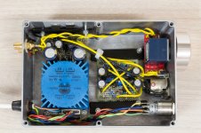
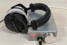
Here're some box shots FYI. I'm no fan of those Hammond cases actually, but they're cheap and easily modified.
Attachments
In 99.9% of the time there are two mistakes --
1. Did not use same part values... including matching of input jFETs. The thd will be high if not matched.
2. The transistor is misplaced in pcb holes... the e-b-c and d-g-s are not placed correctly in the pcb. often the they are reversed ... it will work but not well.... thd will be high. Check the transistor leads and their placement in pcb.
Check the input level being used for your tests.... may be too high?
THx-RNMarsh
Last edited:
Slight OT :
> I wish I could find one as good as the Juli@ with a USB interface...
Jan, take a look at :
RightMark Audio Analyzer test: Juli@ Ch12
RightMark Audio Analyzer test: Terratec Phase X24
We use the Terratec, and you can get one from ebay for little money (<<100€).
http://www.ebay.de/itm/Terratec-Pro...str_Audio_MIDI_Interfaces&hash=item27e3790d51
The problem is to find a laptop with Firewire, but it is still solveable.
Patrick
Richard,
thanks for chiming in!
I'm pretty sure that this is not the case here. I've checked it several times now, consulting several datasheets and measuring the actual devices. Sure, there might still be an error somewhere, since I'm the one who made it and the only one who checked for it, but I doubt it.
Input level was 1VRMS, checked with oscilloscope, attenuated via Alps to yield 1VRMS at the output.
This is likely the culprit. I just tested my remaining FETs (a handful [by count, not by volume])with the circuit you suggested.
The NFETs are 2SK246BL and in the range of 2.4V to 2.6V, which is really far away from the 0.85V you suggested!
The PFETs are 2SJ103BL and in the range of 2.0V to 2.8V, with one device (out of 5....) measuring only 0.62V!
I did not measure the devices currently used in the amp, but it seems to me that getting a big bunch off the 'Bay might be the best thing to do now.
thanks for chiming in!
2. The transistor is misplaced in pcb holes... the e-b-c and d-g-s are not placed correctly in the pcb. often the they are reversed ... it will work but not well.... thd will be high. Check the transistor leads and their placement in pcb.
I'm pretty sure that this is not the case here. I've checked it several times now, consulting several datasheets and measuring the actual devices. Sure, there might still be an error somewhere, since I'm the one who made it and the only one who checked for it, but I doubt it.
Check the input level being used for your tests.... may be too high?
Input level was 1VRMS, checked with oscilloscope, attenuated via Alps to yield 1VRMS at the output.
1. Did not use same part values... including matching of input jFETs. The thd will be high if not matched.
This is likely the culprit. I just tested my remaining FETs (a handful [by count, not by volume
])with the circuit you suggested.The NFETs are 2SK246BL and in the range of 2.4V to 2.6V, which is really far away from the 0.85V you suggested!
The PFETs are 2SJ103BL and in the range of 2.0V to 2.8V, with one device (out of 5....) measuring only 0.62V!
I did not measure the devices currently used in the amp, but it seems to me that getting a big bunch off the 'Bay might be the best thing to do now.

 !
!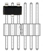
While it is hard to argue with Euvl's boards, I find the idea of soldering it to header pins to be extremely clever. IT is an excellent idea for anyone who might be using that particular smd package and etching boards at home. THank you.Thank you for your offer, but I'll try to solder them directly onto the 1.27mm pin headers first.
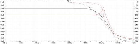
I am away from home so I do not have my Linear Audio copy with me.
But I used the schematic image at the LA website to make up a Spice file for the unity gain version, just out of curiosity.
The frequency response indicates too much gain in HF (> 1MHz) resulting in oscillation or very marginal stability.
Load is 60 ohm resistive.
Is it only a Spice problem and not in reality ?
Or does it only apply to the version with unity gain ?
Anyone did any Spice simulation before ?
I am not posting the Spice files unless Mr. Marsh and Mr. Didden gave their approval.
Patrick
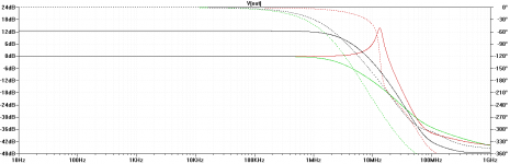
Putting 100pF each between Base and Collector of Q1 and Q2 (I used BC550/560) results in the green trace.
Sims well, but I didn't actually test it.
EDIT: 47pF should be sufficient, yielding a higher bandwidth. Anything lower still shows peaking.
Sims well, but I didn't actually test it.
EDIT: 47pF should be sufficient, yielding a higher bandwidth. Anything lower still shows peaking.
Attachments
Last edited:
- Home
- Amplifiers
- Headphone Systems
- Marsh headphone amp from Linear Audio