I've been trying to start this project for a while. Long story short, I've got a few op-amps and enough stuff to begin putting something together, but I'd like some input and help. I'm limited by working with what I have on hand now. I haven't been able to order anything online for the project and everything I have was paid for by a friend.
Anyway, on to the specifics. I'm looking at creating an amp for my Grado SR80i's, which means I've got the fact that they're low impedance to deal with along with all the other design considerations.
I'm planning on using a 15 volt wall wart (has multiple output voltages actually) which is probably a SMPS.
I'm planning on creating a virtual ground and then creating a buffer circuit out of discrete elements.
I have 2 different op-amps on hand, and I really dont know which one would be better for the amplification process and which would be better suited for the virtual ground (or if there would even be a difference in the vground between them). My op-amp knowledge is pretty much limited to a very basic understanding along with being able to understand some of the datasheet information (I am an electrical engineering student, but it's been quite some time since I covered op-amps and what we did cover was more or less an overview of "here's what they do, here's some places they're used, on to the next subject")
I've got some TLC272ACP and some TL074CN op amps, and 2 2N3904's.
I'm aware this is likely not exactly optimal in any way shape or form, but I consider this a starting point. If I can get something that works out of this, I'll have learned a lot about what I'm working with and maybe in the future when I have money and the means to order parts online, I'll order some better parts to work with.
TL;DR
Got me some TLC272APC, TL074CN, and 2 2N3904's, help me design a working vground/buffer circuit and let me know which would be better in the audio line.
Last edited:
Google cmoy. Click the link to tangentsoft.net
Build a basic cmoy with 2 * 9V batteries using the TLC272.
I'd omit the virtual ground and use the junction of the batteries as ground, but that's my personal preference, there's an arguable risk of damage to the 'phones if one battery is discharged, but the technical performance is better, just make sure you use 2 new batteries from a 2-pack (same sell-by date).
That's it.
Last edited:
I was actually looking at the cmoy as a basis. Quick question: Why is the TLC272 better for the amp than the TL074?
I don't have a battery holder or any money to get a hold of one
I don't really plan on the amp being ultra-portable, which is why I'm fine with the wall wart.
I'm a broke-*** college student, I'm avoiding taking loans so my parents are helping pay for things and any work I can find helps, but I haven't found any work recently so yeah :/
If I'm going with the cmoy design should I add the load side resistor suggested in the addendum for dealing with low impedance phones?
Last edited:
If I'm going with the cmoy design should I add the load side resistor suggested in the addendum for dealing with low impedance phones?
This is a judgement call you have to make.
It's unlikely the DC offset resulting from a virtual ground and low impedance phones will result in damage to the phones, but the Grados are not cheap. You can measure the offset to help you make up your mind.
A large cap (470u) at each output is a better solution than a resistor IMO, any distortion is likely to be less audible than the effect on the frequency response of a resistor, but resistors are cheaper than caps.
You may be able to salvage some components from dead equipment.
Would one of these be any good for you
Under $20.00 DIY Cmoy Hi-Fi Headphone amplifier KIT 18volt power Guaranteed ! | eBay
cheers
Under $20.00 DIY Cmoy Hi-Fi Headphone amplifier KIT 18volt power Guaranteed ! | eBay
cheers
The TCL272 has a decent amount of output current available (+-30mA). I doubt the TL074 would get very far trying to drive your Grados.Quick question: Why is the TLC272 better for the amp than the TL074?
The CMoy schematic I found has quite a high voltage gain (times 10), which seems excessive. IMHO, since you probably don't want (and can't get) more than about 1V output and most sources can give more than 1V input, a unity gain configuration might be suitable.
Since you mentioned having more than one TLC272 available, there's a couple of ways to put extra chips to use:
A) Using 2 opamps in parallel per channel gives you double the maximum output, and lower distortion at lower levels.
B) You could use one chip to make a better virtual ground.
I'm assuming you can get hold of a few resistors and capacitors?
Some ideas below.

Attachments
Would one of these be any good for you
Under $20.00 DIY Cmoy Hi-Fi Headphone amplifier KIT 18volt power Guaranteed ! | eBay
cheers
I kinda wanted to make this as much DIY as possible, and I've already got pretty much everything I need, so that's not really much help at this point. I'm also currently dead broke (well, I got $20 from my grandmother today, but part of that is already going to go towards parking at the college :/)
Thanks for the heads up though. Also, I'm canadian, so that's another $5 shipping. I'll work with what I have now to get something up and runnign and look at improving things later when I have some income.
This is a judgement call you have to make.
It's unlikely the DC offset resulting from a virtual ground and low impedance phones will result in damage to the phones, but the Grados are not cheap. You can measure the offset to help you make up your mind.
A large cap (470u) at each output is a better solution than a resistor IMO, any distortion is likely to be less audible than the effect on the frequency response of a resistor, but resistors are cheaper than caps.
You may be able to salvage some components from dead equipment.
Now I wish I had grabbed a few of the 470uf caps my friend had in his collection just in case. Would paralleling a few smaller caps work instead?
The TCL272 has a decent amount of output current available (+-30mA). I doubt the TL074 would get very far trying to drive your Grados.
The CMoy schematic I found has quite a high voltage gain (times 10), which seems excessive. IMHO, since you probably don't want (and can't get) more than about 1V output and most sources can give more than 1V input, a unity gain configuration might be suitable.
Since you mentioned having more than one TLC272 available, there's a couple of ways to put extra chips to use:
A) Using 2 opamps in parallel per channel gives you double the maximum output, and lower distortion at lower levels.
B) You could use one chip to make a better virtual ground.
I'm assuming you can get hold of a few resistors and capacitors?
Some ideas below.
Thanks for the answer, I had actually been thinking about using two in parallel. Is there any reason not to use the two 2N3904s as a buffer stage? (My transistor knowledge is kinda spotty at best. I've forgotten a lot of what I learned in my AC fundamentals class about transistors because I've basically never had to use them since then).
Paralleling smaller caps to make a larger capacitance works. I'm not a big fan of output capacitors though, so I'd probably be using them for power supply smoothing.I'm also currently dead broke...
Now I wish I had grabbed a few of the 470uf caps my friend had in his collection just in case. Would paralleling a few smaller caps work instead?
As for parts, you mentioned being an EE student. Isn't there an electronics lab on campus where you can try scrounge some components? (Bambi eyes, "Please Sir...") I once got a whole box of stuff from a local college when they were clearing out a store room and tossing the stuff out.
Plan B is to head down to the local garbage dump and look for an old bust radio or something you can strip.
I was thinking about that too. It's a bit awkward making a decent buffer with just one transistor per channel, though. I suppose you could make a simple emitter follower loaded with a resistor to the negative rail, but I'm not convinced the results would be any better than just using the chips.Is there any reason not to use the two 2N3904s as a buffer stage?
p.s. Power supplies from old desktop computers are a goldmine too. If it's still working, you can make a nice standalone 12V power supply. If it's dead, you can strip it for parts.
btw; How are you planning to build this - point to point wiring or Veroboard or...?
Last edited:
I've already tried getting stuff from the college, but it didn't really work out. The EE stuff there mostly focuses on either industrial automation or power generation and distribution, and there really isn't much in the way of parts. I did manage to get a hold of an old oscilloscope for free when they replaced the old ones with fancy new ones, which is kinda nice considering that's what I'm using as a multimeter for the time being (yeah, shoestring budget  )
)
I might just see if there is an old power supply laying around I can scavenge. I'm not a stranger to scavenging for parts. I've got a microwave transformer rated at 120v:4200v sitting around here somewhere from my girlfriend's old microwave.
What effect does output capacitors have vs resistors?
I have a total of 4 100uf caps on me, 2 rated at 25v and 2 rated at 50. The 50V's are from the same company, the other 2 aren't.
I do have a number of small tantalum caps (3 of them read 0.1 35, one reads 105 35). I had a few more and they might still be laying around.
I plan on breadboarding this first and then once the design is finalized I've got some protoboard I can use.
)I might just see if there is an old power supply laying around I can scavenge. I'm not a stranger to scavenging for parts. I've got a microwave transformer rated at 120v:4200v sitting around here somewhere from my girlfriend's old microwave.
What effect does output capacitors have vs resistors?
I have a total of 4 100uf caps on me, 2 rated at 25v and 2 rated at 50. The 50V's are from the same company, the other 2 aren't.
I do have a number of small tantalum caps (3 of them read 0.1 35, one reads 105 35). I had a few more and they might still be laying around.
I plan on breadboarding this first and then once the design is finalized I've got some protoboard I can use.
Wow, nice score with the scope!
The tantalum caps all sound like 0.1uF 35V. They'd be ideal for supply decoupling close to the chips. IMHO, the electrolytics are too small for output coupling, but could be put to good use smoothing the supply. Both the electrolytics and the tantalums are polarised, so have to be put in the right way round.
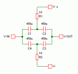
Output caps would protect your phones by preventing any DC getting through to them in the event the amp fails catastrophically. They also roll off the bass below a certain frequency. The -3dB corner frequency is given by: F = 1/(2pi * RC). So for 100uF and 32 ohms, about 50Hz.
Unfortunately, electrolytic caps need some DC voltage across them to work properly. That's easy to organize if you use a single ended power supply, but then you get a big "Thump!" through the headphones (which could damage them) when switching the amp on or off.
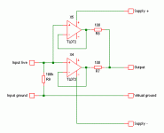
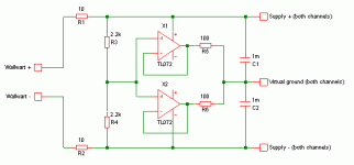
There is a way to get round the problems but it requires more caps. In the scheme shown below, the caps charge up slowly through the resistors, with almost no current through the headphones (ideally none, but the caps won't be perfectly matched).
If you're using 2 or more opamps in parallel, then you need resistors at the outputs to ensure they share the current equally, and to prevent them getting into an argument about exactly what the output voltage should be. The resistors probably also help with stability.
They will have some effect in the frequency response since the output resistance and the headphone impedance forms a voltage divider, and the headphone's impedance varies with frequency.
The tantalum caps all sound like 0.1uF 35V. They'd be ideal for supply decoupling close to the chips. IMHO, the electrolytics are too small for output coupling, but could be put to good use smoothing the supply. Both the electrolytics and the tantalums are polarised, so have to be put in the right way round.
Ideally, you don't want either. If used, high value caps or low value resistors will have the least affect on the sound.What effect does output capacitors have vs resistors?
Output caps would protect your phones by preventing any DC getting through to them in the event the amp fails catastrophically. They also roll off the bass below a certain frequency. The -3dB corner frequency is given by: F = 1/(2pi * RC). So for 100uF and 32 ohms, about 50Hz.
Unfortunately, electrolytic caps need some DC voltage across them to work properly. That's easy to organize if you use a single ended power supply, but then you get a big "Thump!" through the headphones (which could damage them) when switching the amp on or off.
There is a way to get round the problems but it requires more caps. In the scheme shown below, the caps charge up slowly through the resistors, with almost no current through the headphones (ideally none, but the caps won't be perfectly matched).
If you're using 2 or more opamps in parallel, then you need resistors at the outputs to ensure they share the current equally, and to prevent them getting into an argument about exactly what the output voltage should be. The resistors probably also help with stability.
They will have some effect in the frequency response since the output resistance and the headphone impedance forms a voltage divider, and the headphone's impedance varies with frequency.
Attachments
Wow, nice score with the scope!
The tantalum caps all sound like 0.1uF 35V. They'd be ideal for supply decoupling close to the chips. IMHO, the electrolytics are too small for output coupling, but could be put to good use smoothing the supply. Both the electrolytics and the tantalums are polarised, so have to be put in the right way round.
I've always been very careful with caps because I know what happens when things go wrong with them.
I also knew that these tantalum caps were too small. I just wanted to mention that I did have them and could use them. If I'm going to be decoupling near the chips, where should they go?
I realize the more questions like this I ask the more I end up using someone else's ideas to do this, rather than my own, but my electrical theory is rather weak right now because it's been ages since I've been taught most of it, and
to be honest they never taught us anything about **** like pull up resistors, decoupling, etc. etc. I think half of my knowledge that I'm actually using here comes from wikipedia and reading application notes and datasheets online.
Ideally, you don't want either. If used, high value caps or low value resistors will have the least affect on the sound.
Output caps would protect your phones by preventing any DC getting through to them in the event the amp fails catastrophically. They also roll off the bass below a certain frequency. The -3dB corner frequency is given by: F = 1/(2pi * RC). So for 100uF and 32 ohms, about 50Hz.
Makes sense once I think about it. I don't like the idea of bass roll off, considering the Grados don't have amazing bass to begin with.
What affect does the resistor have on the output, other than limiting the current?
Unfortunately, electrolytic caps need some DC voltage across them to work properly. That's easy to organize if you use a single ended power supply, but then you get a big "Thump!" through the headphones (which could damage them) when switching the amp on or off.
There is a way to get round the problems but it requires more caps. In the scheme shown below, the caps charge up slowly through the resistors, with almost no current through the headphones (ideally none, but the caps won't be perfectly matched).
That's an interesting problem, and solution. It's too bad caps are hard to match well.
If you're using 2 or more opamps in parallel, then you need resistors at the outputs to ensure they share the current equally, and to prevent them getting into an argument about exactly what the output voltage should be. The resistors probably also help with stability.
They will have some effect in the frequency response since the output resistance and the headphone impedance forms a voltage divider, and the headphone's impedance varies with frequency.
Is there a way to model this well? I've got a copy of LTSpice that I don't know how to use, and that sounds like a good use for the program. It would be cool if I could lay this out in LTSpice and get a decent simulation of what happens, but I have no idea how to use the program properly.
Also, since I have a bit of money I might head over to the local electronics place and grab some more caps... and hopefully a male to male headphone jack jumper since I seem to have forgotten that that would be a good idea.
I'll update you on whether I have anything new or not after I get back from class today.
If you are going to use two op amps in parallel, the standard resistor/capacitor
power splitter used in the CMoy will not be enough. You need your ground return
to be able to handle the current. If, for example, you have op amps that can put out
a total of 60mA per channel, you should be able to handle 120mA back into the ground.
Thats why using a split battery supply is so attractive.
If you are going to use two op amps in parallel, the standard resistor/capacitor
power splitter used in the CMoy will not be enough. You need your ground return
to be able to handle the current. If, for example, you have op amps that can put out
a total of 60mA per channel, you should be able to handle 120mA back into the ground.
Thats why using a split battery supply is so attractive.
If I was planning on making it ultra-portable, I'd be fine with that, but I don't want to have to keep replacing the batteries. I'm perfectly fine with my amp being plugged into the wall at all times. I mostly plan on using it at home and at my girlfriend's place.
Is there a way I can use my transistors to give the added current capabilities?
I'm used to most everything being NPN. So anyway, you could make the amp using a single biased transistor, using 2 unbiased transistors, or using 2 biased transistors (the latter two options are shown on the linked page, and the first is shown in most any active component textbook).
- Status
- This old topic is closed. If you want to reopen this topic, contact a moderator using the "Report Post" button.
- Home
- Amplifiers
- Headphone Systems
- Starting a headphone amp project, need general help.