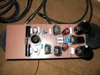
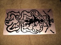
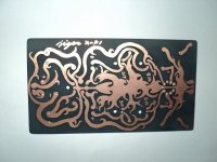
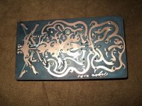
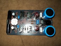
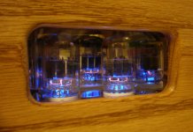
Headphone amp 12AU7 art PCB Design
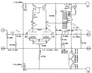
a design published over at DIY Audio Projects NP-100v12: 12AU7 (ECC82) / IRF510 Headphone Amp
append
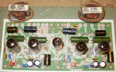
transformer 12V 1-3A
Capacitor
10000uF x2
0.1 UFx2
regulator MC7812
BRIDGE RECTIFIERS BR1006
I'm very bad language.
Sorry, for a little less detailed.
a design published over at DIY Audio Projects NP-100v12: 12AU7 (ECC82) / IRF510 Headphone Amp
append
transformer 12V 1-3A
Capacitor
10000uF x2
0.1 UFx2
regulator MC7812
BRIDGE RECTIFIERS BR1006
I'm very bad language.
Sorry, for a little less detailed.
Attachments
Last edited:
yeah because Erno Borbely really didnt have a clue what he was doing..... neither was the blue hawaii electrostatic headamp a passable idea (project in original DIY form), Kevin Gilmore and John Broksie clearly have rocks in their heads....
I think use whatever is convenient and does the job well.
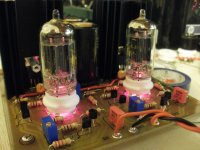
nice work on the PCB art tigersilver! ive often thought about mixing my graphic design/lithography with electronics to do something like that, but i do worry a bit about eddie currents and strange loops caused by the odd shapes
no good? its thought by many to be one of if not THE best headphone amp available and I for one cannot wait to hear my friends fantastic build with his O2 down the bottom (nattonrice, also a member here) kudos Tom its one of the most impressive headphone amp builds ive ever seen
I give you the Blue Hawaii and Nattonrice's slightly modified DIY version using original BHSE PCBs but with a solid state CCS load


I think use whatever is convenient and does the job well.
nice work on the PCB art tigersilver! ive often thought about mixing my graphic design/lithography with electronics to do something like that, but i do worry a bit about eddie currents and strange loops caused by the odd shapes
no good? its thought by many to be one of if not THE best headphone amp available and I for one cannot wait to hear my friends fantastic build with his O2 down the bottom (nattonrice, also a member here) kudos Tom its one of the most impressive headphone amp builds ive ever seen
I give you the Blue Hawaii and Nattonrice's slightly modified DIY version using original BHSE PCBs but with a solid state CCS load
An externally hosted image should be here but it was not working when we last tested it.
Last edited:
 Posted in pm.
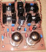
I've done many sand/glass headphone amps, They all worked very well and were black hole quiet, no noise. I tried a low voltage tube differential input mosfet output opamp approach and it is fun to listen too. It uses the tubes heaters as the pull down current on the output mosfet, so the heaters runs at 12 volts with audio AC on it.
I've also done hi voltage tube and Mosfet output designs with DC supplies for the heaters and finally decided on trying a PP tube style amp, should be able to squeeze 1 watt class A out of it.
There are so many ways to accomplish the same goal. Each will have a design bias and may even criticize those who do not follow their beliefs. If you have an idea, try it you may be surprised at the outcome. Always enjoy the process of creation!
Attachments
- Status
- This old topic is closed. If you want to reopen this topic, contact a moderator using the "Report Post" button.