Since I have some Instersil HA-5002 buffers left I want to use 8 - 16 (bridge-parallell) on THE WIRE BAL-BAL instead of 4 x LME49600. My main concern is DC offset, HA-5002 has 20 mV, is it possible to get rid of it? By the way I have 60 Ohm KOSS KSC35, 120 Ohm custom IEM, 120 Ohm AKG K501, 600 Ohm AKG K240DF, 600 Ohm AKG K240M headphones, how to calculate Rf value so I can have the right gain ratio for each of them? I will install a rotary switch to change gain.
I have to, there is no PCB left, good news is 3 to 4 layer PCB is not a problem for factories around here, will cost $$$ though. I have been reading about PPA v1.1 which used paralleled HA-5002 buffers for output, what worked for PPL shall work for Mickey, I hope. If (IF, does not mean I really can) I can eliminate DC offset on the buffers, stuff components as close as possible, optimize the layout for shortest signal path, will it still be a nightmare? Any idea how to calculate Rf value for different headphones? I will switch only when the amp is off.
My main concern is DC offset, HA-5002 has 20 mV, is it possible to get rid of it?
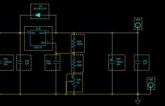
Based on looking at the BAL->SE WIRE circuit (I couldn't find the BAL->BAL version)...
Because the buffer will be within a feedback loop with an opamp the output offset will be controlled by the opamp's input offset voltage, input offset current and input bias current. If you stick to using 4 and forget trying to parallel them then the output offset should be no worse than that of THE WIRE
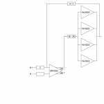
but buffers in parallel can lower the distortion, lower output current for each buffer and make the 5002s harder to kill  if i insist then DC servos are a must right? seems like tl074 is just for such situation stupidness continues, if i use 4 buffers in parallel shall i change the 330µF caps to 1500µF or higher and use 4x PSU as well? @counter culture, THE WIRE schematic is right here, please see page 3 for BAL-BAL.
if i insist then DC servos are a must right? seems like tl074 is just for such situation stupidness continues, if i use 4 buffers in parallel shall i change the 330µF caps to 1500µF or higher and use 4x PSU as well? @counter culture, THE WIRE schematic is right here, please see page 3 for BAL-BAL.Mickey,
I'm not sure this will work well.
First you could have some issues with both inputs and outputs. You have to watch the outputs on the 5002's and while I use them often (hard to beat for the price on Ebay) over the LME49600, etc. you have to address the input bias and make sure the outputs don't oscillate which can happen if the load impedance is to high.
These guys are made to drive loads and they do it well but be careful how you set them up.
I'm using a new bias scheme over the 5002 project now and you can see it in the May issue of aX next month where I used the 5002's driven by THS4631's.
Jan Didden pointed out the 4631's to me and I think they work well driving the 5002's especially if you want to inject some gain into the circuit. I still like the 5002's on outputs though.
I would try it with 100 ohms into ONE 5002 , not 4 to see what it looks like before I started multiplying the 5002's. Also what value are you using for the current limit on the 5002's?
There's a specific formula for that- see the data sheet.
Best,
Rob
Last edited:
I think you should stop calling it the wire. the only similarity is you are using the opa1632 and a buffer of some sort somewhere, there are numbers of other amps dating back years that used the opa1632 and a buffer and they werent called the wire.
sorry, i will call it THE PIPE from now on
sorry, i will call it THE PIPE from now on
Good one!
One more thing, to keep the outputs from conflicting with each other when you use parallel arrangements it's best to put a small resistor on each output leg of your buffers. I used .5 ohms on the the 5002 amp.
Rob
sorry, i will call it THE PIPE from now on
why? something on your mind?
he already has one that has 8 parallel buffers per channel to power speakers and crazy hungry headphones (for insane people)
its still called the wire...
no objection to the project, should be fun, though the buffers are not available everywhere so that could be an issue if you got PCBs done, I just saw no resemblance to the schematic, the parts, or the designer; so using his name doesnt make sense to me
Last edited:
I'd like to see the sch. for the "wire".
I looked at the LME49600 and it does look good but I haven't experimented with it.
The price is slightly higher than the 5002 (Avnet $4.67 for 26 or more) which does work well but I like the fact that the LME49600 has internal current limiting which would eliminate the limiting resistors in my 5002 design.
I will say the 5002 does sound good as an amp. I'm revising the input to eliminate the drive 5002 scheme but I'll be using the THS4631 over the LME49710 as it has a better slew rate and I value that over low distortion figures.
I'm going to order some LME49600's to see what they will do. I'll bet the THS4631 driving the LME49600 will be a hard combo to beat but I'd love to hear views on it from you builders.
Rob
dang how did i miss this? better read more before i reinvent the wheels heh
correct =) the LPUHP, yet another winner of an opc project, i'm just winding up parts for the GB, no boards left but you should be able to pull enough info from his design. doesnt have balanced output, only input, but little oir no tradeoff, never seen a speaker amp measure like that, cant wait to hear it
Last edited:
robaroni, schematics for 'the wire' are posted in the relevant threads as well as the build wiki that opc wrote.
Thanks,
Interesting design, I'd make some changes, but I like it.
The power supply would benefit from LM1084's and the 330uf caps shouldn't be on the 317 output side.
Since it looks like the pwr xformer is a dual secondary, which is a good idea in split supplies, you can use two positive regulators like the 1084 that will work up to 5 amps. The reason you want to a reg with more current capacity to reduce the drop out voltage which is relative to current, the other thing is device dissipation. A regulator may be able to internally regulate to 1.5 amps but the device can only dissipate so much, especially with the small heat sinks on his power board.
Also, you don't want to run relatively large capacitors on three terminal regulator outputs, they defeat the benefit of the regulator. The place you want to put the beefy caps is on the input side of the regulators. 1200uf is to low, 10k is a better choice. Ideally what you want on the xformer side is a voltage that is enough above the peak secondary current so that it never drops below the secondary voltage at that current. ( taking into account the insertion loss of regs at 1.2 volts)
The primary cap keeps the ripple voltage high enough that you can keep the primary voltage as low as possible. When you do this you keep the device dissipation low and that's what you want because then the regulator functions best.
The protection diodes keep the regulator from 'cooking' if the secondary voltage ever exceeds the primary voltage. The internals of the reg can't take that and the thing that causes a secondary voltage from exceeding the primary voltage is high secondary capacitor values, which is another reason to keep them low (the 49600 has a pretty good PSRR and the 10uf bypass on each leg the specs advise is fine)
On the power board you want to keep the caps away from the heat sinks as much as possible too, that causes premature cap failures.
I'd change the 1632 also, it only has a slew rate in the 20volt per uS range and defeats the benefit of the wonderful 2k slew rate of the 49600.
Nice idea, I'd like to hear it compared to my 5002 amp., I'll bet it gives it a run for its money!
Rob
Attachments
higher slew rate then the 1632/9600 is purely academic for audio, as with your power supply 'improvements' the regs barely break a sweat as they are and the caps on the output are pretty meaningless given the local decoupling caps do the work for supplying transient demand and NEVER the regulator, likewise increasing the input caps to that size produces no benefit, only higher inrush. the measurements of these amplifiers and sound is superb, bettering the capability of an audio precision system 2 to measure it (at better than -145db from memory, maybe much better I cant remember) interested to see your improvements =) using 2 x 1084 is possible, but raises the ground impedance to the level of the reg/output caps, yet you suggest to make them smaller?
if talking about the lpuhp now not the headphone amps?, the current is higher yes, but the slew rate still is not limited by the supply
I understand the need/want to tweak, but when a design is already pushing the limits of the capability to measure, let alone hear, best realise further efforts are self serving at best. its a design that was made to have wide azppeal and high perfcormance at a decent cost, I suggested improvements to the supply and even tried some, but it made no difference whatsoever. opc realizes some will want to use different supplies and you will not please everyone in this area, so he left it like this and people can use what they choose
I use lt1085/1033 on mine but also tried a sigma22, A123 lifepo4 batteries (these are wicked and I still use them in my portable version) and a coffin minigold high current super regulator. I think I hear a difference with the batteries, but the others just took up more space
FWI in the portable version I use 'dual mono' LT3032 low noise bipolar LDOs with 4 x A123 batteries feeding 600uf of panasonic 'special polymer/SP' caps per rail and only 150 on the output. the LDOs are only capable of +/-120ma each max, use a small section of copper pour for heatsink only and the amp powers JH13 very low impedance custom in ear monitors or HD600 with no problems at all.
Last edited:
higher slew rate then the 1632/9600 is purely academic for audio, as with your power supply 'improvements' the regs barely break a sweat as they are and the caps on the output are pretty meaningless given the local decoupling caps do the work for supplying transient demand and NEVER the regulator, likewise increasing the input caps to that size produces no benefit, only higher inrush. the measurements of these amplifiers and sound is superb, bettering the capability of an audio precision system 2 to measure it (at better than -145db from memory, maybe much better I cant remember) interested to see your improvements =) using 2 x 1084 is possible, but raises the ground impedance to the level of the reg/output caps, yet you suggest to make them smaller?
if talking about the lpuhp now not the headphone amps?, the current is higher yes, but the slew rate still is not limited by the supply
I understand the need/want to tweak, but when a design is already pushing the limits of the capability to measure, let alone hear, best realise further efforts are self serving at best. its a design that was made to have wide azppeal and high perfcormance at a decent cost, I suggested improvements to the supply and even tried some, but it made no difference whatsoever
I see you amended your statement.
First, the slew rate of the LME49990 is relatively low (see snippet) thus the overall slew rate is the lowest slew rate of the complete circuit. The 49600 slew rate of 2000 is basically negated. The THS4631 has a slew rate of ~1000 V/us, thus the total circuit is raised from 22 V/uS to over 1000, a substantial difference.
The PSRR of the LME49600 is around 75db, please explain your -145 statement. (see graph).
"Breaking a sweat", not with a 75% efficiency and +/-15V supply at 15 watts out they're not.
Output capacitors are directly responsible for transient time. What is the purpose of the 330uF cap on the output? Why is it needed? Look at Nationals circuit examples and show me where they use high value caps on the output side of regulators? Talk to the engineers, I have, on several occasions and with respect to several regulators.
Using a dual configuration with one side driving pos. and the other side driving neg. has several advantages. First we eliminate the the different regulator types which gives better rail to rail consistency. (If you look at the specs of the 337 and the 317 you will see that they have different line and load regulation figures, that means that the rails will not be equal throughout the load line). Secondly we double the rectifiers dividing inrush current load by 2. Impedance isn't the issue, we're not changing what the amp sees.
I never said slew rate was limited by supply.
We use High value caps after the diodes to keep the ripple low at higher currents, that allows us to keep the ratio of the input voltage to the output voltage of the regulator as low as possible. Because regulator criteria is a product of heat dissipation we want to keep them as cool as possible. In a headphone supply this, of course, is less of an issue and in this application I can see your point that the 317/337 configuration is fine. In a power amp using the 9600 configuration the 1084 supply is a better option.
One more thing, you can not say they sound is isn't any better, this is a subjective assessment and subjective assessments are opinion. We strive to make the best technical design. We always strive to surpass our previous designs regardless whether we can hear them or see them on graphs or not. Without this perspective we never move forward, we only settle for what has already been achieved.
Rob
FWI in the portable version I use 'dual mono' LT3032 low noise bipolar LDOs with 4 x A123 batteries feeding 600uf of panasonic 'special polymer/SP' caps per rail and only 150 on the output. the LDOs are only capable of +/-120ma each max, use a small section of copper pour for heatsink only and the amp powers JH13 very low impedance custom in ear monitors or HD600 with no problems at all.
Looks like an interesting regulator, I'll have to try it, thanks. Notice the capacitance on the output of their example? 10uF
The specs say +/-150ma.
You're running the amp with the 12 volt version of the regulator? That would be 12 * .15 = 1.8 watts each side, That should drive just about every phone.
Rob
Last edited:
I guess the -145dB that qusp was pulling from memory is related to these measurements - http://www.diyaudio.com/forums/head...-headphone-amplifier-pcbs-90.html#post2790611
That was the latest set of measurements I could find in that thread. I personally haven't spent much time considering tweaks to the performance because I know the limitations in my system are elsewhere.
That was the latest set of measurements I could find in that thread. I personally haven't spent much time considering tweaks to the performance because I know the limitations in my system are elsewhere.
- Status
- This old topic is closed. If you want to reopen this topic, contact a moderator using the "Report Post" button.
- Home
- Amplifiers
- Headphone Systems
- Using HA-5002 instead of LME49600 on THE WIRE