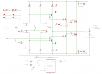
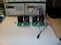
Thor, an all discrete Lateral FET Class A Headphone Amplifier.
Thor, an all discrete Lateral FET Class A Headphone Amplifier.
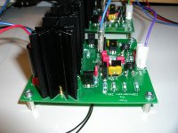
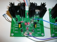
PCB design for the amplifier modules is finished and the modules have been mounted and are now up and running.
180 mA bias, supply from +/- 12 to 18V. Gain is set at x2 but will happily work at x10 gain if needed.
DC coupled with a DC Servo to handle offset issued. DC Offset stays at around +/- 1mV even after several hours off playing.
The same stability is seen in the bias, once it stabilizes at around 180 mA it doesn't drift more than 10 mA in each direction.
Modules are simple to get up and running. Match the input JFET's to around 6mA IDSS, use a pot to trim the Lateral FET output bias, read the pot value and then use the fixed value resistor that comes closest and use that as your bias resistor.
Upcoming additions are a No-thump board, the design is done, just need to get the boards manufactured, mounted and tested. 2 Sec turn on delay and AC detection that turns off the output relay when AC to the amplifier supply is turned off. No thumps/pops/clicks in this amp.
Lastly a supply board, nothing special, just your standard LM317/LM337 combo but with a decent amount of capacitance both before and after the regulator. This design is done as well, just need to get the boards manufactured, mounted and tested.
Thor, an all discrete Lateral FET Class A Headphone Amplifier.
PCB design for the amplifier modules is finished and the modules have been mounted and are now up and running.
180 mA bias, supply from +/- 12 to 18V. Gain is set at x2 but will happily work at x10 gain if needed.
DC coupled with a DC Servo to handle offset issued. DC Offset stays at around +/- 1mV even after several hours off playing.
The same stability is seen in the bias, once it stabilizes at around 180 mA it doesn't drift more than 10 mA in each direction.
Modules are simple to get up and running. Match the input JFET's to around 6mA IDSS, use a pot to trim the Lateral FET output bias, read the pot value and then use the fixed value resistor that comes closest and use that as your bias resistor.
Upcoming additions are a No-thump board, the design is done, just need to get the boards manufactured, mounted and tested. 2 Sec turn on delay and AC detection that turns off the output relay when AC to the amplifier supply is turned off. No thumps/pops/clicks in this amp.
Lastly a supply board, nothing special, just your standard LM317/LM337 combo but with a decent amount of capacitance both before and after the regulator. This design is done as well, just need to get the boards manufactured, mounted and tested.
Attachments
Last edited:
interesting, as someone else in the other thread said, pretty straight forward mod to make differential in/out and i might just try it with some left over alfets as i have everything else in my parts bin. what transistors have you used in the network T5-T10? BC550/560 ok?
Last edited:
what transistors have you used in the network T5-T10? BC550/560 ok?
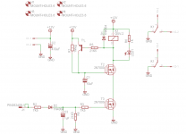
I used Fairchildsemi KSC3503 and KSA1381.
Well, sometimes **** hits the fan.
The basic design is good, however I might have been a little too focused on getting very low THD-20 distortion numbers at the cost of stability in some cases.
2 test headphones worked very well, but my own cheap Sennheiser HD415 headphones caused some instability. Switching the 2 compensation caps from 10pF to 39pF fixed it right up. THD-20 went from 0.0005X% to 0.0008X% in simulation with 5.6V p-p output.
So I would advise anything from 39pF to 150pF as compensation caps. 150pF still gives a low THD-20 0f 0.001X% in simulation with 5.6V p-p output.
If you want to be on the 100% completely safe side then use 150pF, otherwise lower values could work just as well, depending on your headphone and the headphone cabling.
Revised schematic attached.
PS : It sounds absolute fantastic with just a pair of cheap Sennheiser HD415 headphones.
Attachments
Last edited:
nice, still perfectly good numbers with 150pf, my headphones and cables are all pretty low capacitance, I dont have a scope but i guess i can just check for current draw or just play it safe with 150, you used np0, mica or styrene?. ok we'll see how much drive i have to make more amps after the current crop of projects, i'm trying to get some perspective.....
Yes, the numbers are still perfectly fine with 150pF compensation caps. However, it is just a simulation, reality might show numbers that are higher.
I do have access to 2 different audio analyzers at work, someday I might hook up my amp boards and see what they can really do in a real world test.
Checking for current draw is most likely the only thing you can do without a scope. But if you play it safe and go with 150pF compensation caps I cant really imagine it going wrong.
I use Silver Mica.
why such huge output Q?
2sj76, 2sk213 are more appropriate for headphone drive than the 7 A devices
+/-12 V supply is also a little small for these discrete parts, most headphones I know of that need several 100s of mA – as implied by your bias current
stability with output loading - most often cable C - can be improved with a few uH series inductor (parallel with R for damping if you care about 100 kHz ringing) - can be air core if you obsess about such things
why such huge output Q?
2sj76, 2sk213 are more appropriate for headphone drive than the 7 A devices
+/-12 V supply is also a little small for these discrete parts, most headphones I know of that need several 100s of mA – as implied by your bias current
stability with output loading - most often cable C - can be improved with a few uH series inductor (parallel with R for damping if you care about 100 kHz ringing) - can be air core if you obsess about such things
In general 32 Ohm headphones do not need alot of voltage across them, but they do like some current reserves. On the other hand 600 Ohm headphones do need alot more voltage across them, but do not really need that much current.
I personally feel that +/- 12V and a few hundered mA of bias current is a good balance. Besides, higher bias gives lower distortion.
I also like to oversize things and using a pair of big 7 A devices does not cost much more than the significantly smaller and less powerful 2sj76, 2sk213 Lateral FET's. Also, the 2sj76, 2sk213 Lateral FET's are hard to come by, while I on the other hand have a good source of the 2SK1058/2SJ162 Lateral FET's from a supplier where I can get them for about 5$ a piece.
With regards to stability I have already considered both an output resistor or an output inductor//resistor but decided that increasing the compensation caps would be far simpler and work just as good.
Bottom line is that it works and sounds great as well.
My own personal goals for this headamp have been more than met.
")
higher V also gives less distortion - can avoid instability from device parasitics that increase near saturation - at least several V extra, >2x Vth is a good idea
but as a intellectual puzzle can you tell me why if 2-3x over bias/current reserve is so good why isn't more V margin as important
since by publishing the circuit here you are implying others might want to build it - it is good to spell out the assumptions, limitations, particularly if the circuit is "optimized" for a particualr headphone
I wouldn't call ~7 Vrms to be the end point for headphone amp Vout
another point is that other builders would want to know how closely did you match input Q - how much performance degrades with mismatch, Vth can still vary despite Idss match
Last edited:
but as a intellectual puzzle can you tell me why if 2-3x over bias/current reserve is so good why isn't more V margin as important
since by publishing the circuit here you are implying others might want to build it - it is good to spell out the assumptions, limitations, particularly if the circuit is "optimized" for a particualr headphone
I wouldn't call ~7 Vrms to be the end point for headphone amp Vout
another point is that other builders would want to know how closely did you match input Q - how much performance degrades with mismatch, Vth can still vary despite Idss match
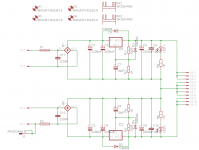
It is mainly built for 32-150 Ohm headphones but someone who wants to drive 600 Ohm headphones or need more output voltage could just increase the supply to +/- 18VDC instead of +/- 12VDC. +/- 18VDC is the limit of the DC Servo Opamp.
Input JFETs are matched to around 6mA with each pair being within 0.1mA of each other and the N and P channel pairs being with 0.2mA of each other.
This is just a fun little project, done in my spare time. I shared it so other people could build it if they want or get some inspiration from it.
It is what it is.
Last edited:
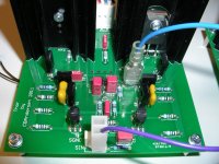
I took a few pictures today.
One will notice is that I did not make the correct Eagle model for the Silver Mica compensation caps so I had to bend the legs a little and they are also a little too close to the transistors than I would normally want them to be.
However the rest of the PCB layout works very well.
One will notice is that I did not make the correct Eagle model for the Silver Mica compensation caps so I had to bend the legs a little and they are also a little too close to the transistors than I would normally want them to be.
However the rest of the PCB layout works very well.
Attachments
Last edited:
It is mainly built for 32-150 Ohm headphones but someone who wants to drive 600 Ohm headphones or need more output voltage could just increase the supply to +/- 18VDC instead of +/- 12VDC. +/- 18VDC is the limit of the DC Servo Opamp.
Input JFETs are matched to around 6mA with each pair being within 0.1mA of each other and the N and P channel pairs being with 0.2mA of each other.
This is just a fun little project, done in my spare time. I shared it so other people could build it if they want or get some inspiration from it.
It is what it is.
You could use the LSK389 for the N channel pair. No equivalent P channel type is currently in production as far as I know.
You could use the LSK389 for the N channel pair. No equivalent P channel type is currently in production as far as I know.
Thats the problem, no dual P-channel in production. I would rather just match both the N and P channel JFET's than use a dual N-channel JFET+2 matched P channel JFET's.
I'm a little OCD when it comes to doing schematics and layouts, I like it to be as symmetric as possbile. Using 1 dual + 2 single JFET's just isn't symmetric enough.

Last edited:
Thats the problem, no dual P-channel in production. I would rather just match both the N and P channel JFET's than use a dual N-channel JFET+2 matched P channel JFET's.
I'm a little OCD when it comes to doing schematics and layouts, I like it to be as symmetric as possbile. Using 1 dual + 2 single JFET's just isn't symmetric enough.
Well, if you were open to NPN and PNP matched pairs in the same package, then Analog Devices makes these things.
Well, if you were open to NPN and PNP matched pairs in the same package, then Analog Devices makes these things.
Well, after I found the complementary floating JFET input stage topology I'm never going back to BJT's for input stages and output stages. For VAS, drivers and other stuff I would still use them.
- Status
- This old topic is closed. If you want to reopen this topic, contact a moderator using the "Report Post" button.
- Home
- Amplifiers
- Headphone Systems
- Thor, an all discrete Lateral FET Headphone Amplifier.