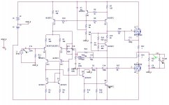
BTW, are you sure that symmetric drain resistors in the input stage give best performance? Normally I'd think that R4/5 < R15/18 would result in better symmetry.
Maybe they do, maybe not. To be honest I have not really looked into using different drain resistor values for R4/5 and R15/18.
We are already talking about a THD-20 that is less then 0.001% at 5.6V p-p in simulation.
Fiddling around with the resistors might a help a little but I personally feel that at these already insanely low THD-20 levels not much is to be gained.
Just came across this thread. The OP's design is very similar to what I am considering for a headphone amp. I tire of the op-amp based designs that seem to be the norm in headphone amps.
I am working on a very similar design, but I am including (at least the option for having) the driven input cascode on the LTPs. This is mainly because the gain is apt to be quite low. I haven't settled on the output drivers yet, other than they will certainly be biased in class A.
The big difference in what I am looking at is the power rails. I am thinking of about +/- 35 volts! I know many people are now calling me a complete whacko, but after a quick web survey, I see headphones range from about 4 Ohms (rarely) to as much as 600 Ohms (fairly often), with maximum power ratings of up to 1 Watt.
1W at 600 Ohms requires +/- 35 volt swing.
1W at 4 Ohms requires 710mA peak current, (355mA bias for class A).
So an amp that is capable of driving all phones to their maximum rating should be capable of +/- 35 V swings and have a bias of 355mA!!!!
I would be inclined to compromise on the low impedance side, since it looks like 4 and 8 Ohm headphones have gone the way of the dinosaur, but a higher bias may improve the sound even where the current isn't needed.
My present headphones are AKG701s, so this thing could be downright dangerous connected to them, so some sort of gain switch or maybbe even an "impedance switch" that could set the maximum voltage swing might be a requirement.
Does anyone know of a fairly comprehensive survey of headphone impedance and power requirements? The highest voltage requirement I have come across is the Beyerdynamic DT 100, which is available in 400 Ohms impedance with 1000mW power handling capability. This would require 57 Vp-p signal swing (+/-28V rails)! They also list the SPL at 94dB @ 1mW. So 1000mW would be 124 dB SPL, which would cause nearly instant hearing damage, so maybe no need to be quite that nuts.
Are there any 600 Ohm phones that are rated to take 1W?
Terry
there are 50 Ohm headphones that "need" 6 Wrms, ~= +/- 25 V, 500 mA
but that’s with pricey Orthodynamics and to reach 120 dB SPL peaks
its unreasonable to try to cover the 4 orders of magnitude that all categories of dynamic headphones sensitivity range over with one amp
since this is DIY you should be happy for the opportunity to build several amps customized to a small range of headphone sensitivity, Z
TerrySt,
I decided to drop the gain to about 5.5x and add the cascode setup to the input as well. Spice actually gave a slightly decreased THD20 with the cascode even though it apparently does not model the effect which causes the increased HF distortion at low gain.
The only downside to this that I can see is the increased noise from the larger feedback resistors; to decrease them you'd need to drop the input resistor as well to avoid upsetting DC balance and increase your input cap which isn't so great.
I'll probably settle on including the cascode and a gain of maybe 7-8. I'm going to use an opamp preamp so I could potentially decrease the amps feedback and input resistors (and therefor input impedance) to decrease noise, but I think I'll gauge the noise performance by ear when I'm building and hopefully I won't need to.
Attachments
I'm thinking of including the driven cascode in the layout, but of course if bench measurements or listening tests show it doesn't help or causes more harm than good, it can always just be removed. Simulations do show that there is a compromise between distortion and the transient response with respect to the value of the capacitor that is used to couple the drive signal to the bases of the cascodes.
I haven't started researching the noise yet. I suspect that noise could be a major issue with a headphone amp, so I'm not ignoring it, just haven't gotten that far yet.
I also have included a cascode for the VAS collector, although again, it would be easy to drop this if it doesn't really help.
Right now my design is basically from the Cordell book, but with the addition of the driven cascode on the input LTP. I haven't decided on the output stage yet, although it will certainly be class A. I may end up with something very much like your approach.
As mentioned a couple of times earlier, a gain switch is probably a good idea unless you want to target a certain headphone. Also, if I go with the plan to have high enough rails to drive 600 Ohm phones to high levels, some sort of "impedance" switch that limits the output voltage swing to a reasonable level based on the headphone impedance might be wise.
Terry
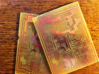
Got one populated, but i screwed up  when I printed the transfer for the PCB's and didn't invert it correctly in one axis. Everything else was fine, just had to mount all the TO92 stuff 'backwards', but the mosfets pin out doesn't allow that. Might have to put the on the bottom of the board.
Yeah, it'll be interesting; the power supply routing is definitely sub-optimal, I pretty much went around the outside because I got impatient. Hopefully the current levels will be low enough that no hum gets into the signal...
when I printed the transfer for the PCB's and didn't invert it correctly in one axis. Everything else was fine, just had to mount all the TO92 stuff 'backwards', but the mosfets pin out doesn't allow that. Might have to put the on the bottom of the board. Yeah, it'll be interesting; the power supply routing is definitely sub-optimal, I pretty much went around the outside because I got impatient. Hopefully the current levels will be low enough that no hum gets into the signal...
Attachments
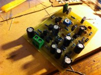
Got it running, everything is as expected, DC offset is reliably 3mV without a DC servo. The issue that i came across was that oscillation was occurring unless I scrapped the twin pole comp and significantly increased the value of the comp capacitor. The oscillation was at about 1MHz and was only about 2vpk-pk with +/-15v supplies, so it was strangely controlled and reliable. I don't like the idea of having to roll off gain so early; i guess this could be due to the low net gain/ high feedback situation or poor pcb layout or a combination of both, any suggestions?
I'm still just in 'simulation mode', but I'm also fighting stability issues. Mainly because I added a cascode on the VAS collector also. The darlington VAS plus the cascode makes a fairly long local feedback loop. I have been able to stabilize it by adding a cap from the collector to the base of the VAS transistor (Q9 in your schematic above). I'm not sure I'm OK with that approach. I will continue to study it. You might try it and see if it lets you decrease the feedback around the VAS or maybe even get back to the Twin pole comp.
Also, I find that C15 value is critical for transient resonse (at least in simulations). Too large a value cause some bad overshoot on fast rise time transients. Too small reduces the distortion benefit.
Maybe some local bypassing near the amp would help?
You could try increasing the global feedback to see if that helps, but it sounds like it may be a local issue (around the VAS). Increasing the global gain will show if it is a global loop issue or a local one.
Terry
You guys may want to try a CCS instead of an emitter resistor on the first transistor in the Darlington VAS (R14). I found this entirely eliminated severe common-mode distortion introduced with the Darlington. (A differential VAS that I also tried suffered from the same problem, presumably because it only used a tail resistor.)
Yeah, Darlington + cascode may be pushing it a little.
Oh, and regarding LTP collector resistors: I found that once the LTP was properly balanced, resistor value on the unconnected leg pretty much does not matter.
My simulated discrete opamps so far are about on the level of Samuel Groner's SGA-SOA-2, with a Darlington VAS. Not bad and quite well-behaved when driving loads, but matching a good integrated opamp in transfer linearity seems difficult so far. Really a lesson in modesty.
Spent a few hours looking for the problem and found that by increasing the emitter resistors of the input pair to reduce their transconductance allows for the use of a more conventionally sized comp capacitor of about 150pf with stability into all the loads I tried. Increasing them to 220r worked for me. I was pretty sure it wasn't a vas problem, because when I cut out the output stage by connecting the output of the vas to the feedback node it was perfectly stable previously. Anyway I think the original value of 20r was just too close to the theoretical minimum, even though self suggests that its mathematically correct he still uses 100 or 220 in his designs
I like the idea of loading the vas darlington with a ccs, but since the vas is already wrapped solidly in global or local fb, do you think you'd get a measurable decrease in total THD? Also it would push the negative peak swing of the vas another .65v away from the rail voltage.
finally bothered to do the math, (which I really should have done earlier) to maintain a "safe" value of 30dB of NFB at 20kHz with the NFB network setting the closed loop gain at ~7.5 as it is and emitter resistors of 20Ohms giving a large gm for the input pair, Cdom would have needed to be just over 1000pF. Decreasing the input stage gm by increasing Re to 270Ohms allows a Cdom of 120pF to maintain this criteria. This was very close to the value for Cdom I found to be necessary for stability in practice, and seems a better solution to me to avoid potential slew limiting from a large Cdom.
All I can say is that it did make a difference here when subjecting my opamp model to Samuel Groner's common-mode linearity and transfer linearity tests. With a 2k2 resistor, common-mode linearity was almost 20 dB worse (-43 dB vs. -62 dB, 10 kHz, ~+20 dBu) and in fact worse than with a simple VAS, which evened out when using an - admittedly ideal - current source. (It was a pretty standard pnp input LTP-VAS-EF topology otherwise.)I like the idea of loading the vas darlington with a ccs, but since the vas is already wrapped solidly in global or local fb, do you think you'd get a measurable decrease in total THD? Also it would push the negative peak swing of the vas another .65v away from the rail voltage.
I don't think VAS voltage swing is affected by using a CCS load on the first transistor, as long as it is a simple CCS that is content with Vce,sat. It only ever has to go as low as Vbe of the 2nd transistor anyway.
One more funny effect I saw was that well-meaning filtering of supplies within the amp actually made distortion worse when it was faced with non-negligible supply impedance. Possibly VAS and output transistor are forming sort of a CFP.
I also simulated the first complementary (though bipolar) LTP input headphone amp of my own today, similar to the Rotel power amps of yore (I used a very richly biased EF2 output instead of the triple EF employed for driving loudspeakers, plus current mirrors on the LTP in spite of the doubts re: VAS current - a VAS emitter resistors seems to sort that out reasonably well). Getting the affair stable with a Darlington VAS proved a bit tricky, but even with a standard VAS (which was good enough for extremely low distortion at hundreds of watts), I must say performance is excellent as long as there's enough supply headroom - I went for +/- 22 V.
We're talking <0.001% at 10 kHz@20Vpp into 600 ohms and still very little distortion into lower-impedance loads, at a relatively modest 30 mA of output transistor bias. When unity-gain compensated and run at a gain of 2, 10 Vpp into 600 ohms is claimed to give 0.000034% THD, though I bet the unmodeled Early nonlinearity would mar this figure. Low enough, I say.
Seems to be a pretty efficient topology that's not too hard to get going, no wonder it's popular in higher-powered speaker amps. My folded cascode efforts so far, while finally working by now at least, aren't nearly as convincing at similar parts count (though I know opamps like the AD797 exist, so it must be possible to get first-rate performance). This complementary thing is the first concept I've tried that can at least hope to match first-rate opamps.
Last edited:
- Status
- This old topic is closed. If you want to reopen this topic, contact a moderator using the "Report Post" button.
- Home
- Amplifiers
- Headphone Systems
- Discrete, Class A Lateral MosFET Headphone amp (not another follower buffer!)