Hey guys,
I've been wanting to build a headamp for my AKG701's, which need a bit more power, for a while now but haven't seen any schems that really caught my eye.
I know the currently popular opamp based designs (eg the Wire and O2) perform exceptionally well, but I find them a little boring, and browsing Rod Elliot's site and coming across his Project 101 mosfet output power amp inspired me to design a discrete, class A mosfet headamp.
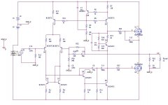
The front end is based off Self's poweramp designs sans driver stage, and the output stage consists of EXC10N20 and EXC10P20 Exicon audio Lateral Mosfets. I used these because I've had a couple of pairs lying around, but any lateral audio mosfets can be used.
The power requirements obviously mean this thing won't be portable but I'm hoping the performance will rival the Opamp based designs but with far more power.
Not included in the schem are the power supply + decoupling caps and diode protection on the mosfets.
As yet I have not begun the build but have run a few simulations and started to optimize the component values and the results look very promising
Output from this design is realistically only limited by your power supply; as shown the quiescent current in the mosfets is ~100mA which will give an entire watt of headroom with exceedingly low distortion. Max power for my phones is 200mW so I'll never run out of headroom (but I might blow them up) and the Iq could be lowered to 70 or 80mA. When too more current is drawn the amp will operate in class B up to the voltage limitation of the supply.
Output impedance is tiny.
Frequency response in sims is flat (+/-1dB) from less than 10Hz to in excess of 150kHz. THD according to Pspice is looking good but I am always skeptical of THD simulations, and I would be surprised if it turns out to be as low as the opamp headamps.
Gain is set at around 11.
The design, with few alterations, can be turned into a class A or AB power amp up to around 100WRms by changing only the Iq, using small sig. transistors capable of handling the voltage, a bigger power supply and sufficient heatsinks.
I know the power mosfets are huge overkill for this project, but I've been wanting something to do something with them for ages...
Anyway, If anyone has any feedback, observations or criticisms let me know!
I've been wanting to build a headamp for my AKG701's, which need a bit more power, for a while now but haven't seen any schems that really caught my eye.
I know the currently popular opamp based designs (eg the Wire and O2) perform exceptionally well, but I find them a little boring, and browsing Rod Elliot's site and coming across his Project 101 mosfet output power amp inspired me to design a discrete, class A mosfet headamp.
The front end is based off Self's poweramp designs sans driver stage, and the output stage consists of EXC10N20 and EXC10P20 Exicon audio Lateral Mosfets. I used these because I've had a couple of pairs lying around, but any lateral audio mosfets can be used.
The power requirements obviously mean this thing won't be portable but I'm hoping the performance will rival the Opamp based designs but with far more power.
Not included in the schem are the power supply + decoupling caps and diode protection on the mosfets.
As yet I have not begun the build but have run a few simulations and started to optimize the component values and the results look very promising
Output from this design is realistically only limited by your power supply; as shown the quiescent current in the mosfets is ~100mA which will give an entire watt of headroom with exceedingly low distortion. Max power for my phones is 200mW so I'll never run out of headroom (but I might blow them up) and the Iq could be lowered to 70 or 80mA. When too more current is drawn the amp will operate in class B up to the voltage limitation of the supply.
Output impedance is tiny.
Frequency response in sims is flat (+/-1dB) from less than 10Hz to in excess of 150kHz. THD according to Pspice is looking good but I am always skeptical of THD simulations, and I would be surprised if it turns out to be as low as the opamp headamps.
Gain is set at around 11.
The design, with few alterations, can be turned into a class A or AB power amp up to around 100WRms by changing only the Iq, using small sig. transistors capable of handling the voltage, a bigger power supply and sufficient heatsinks.
I know the power mosfets are huge overkill for this project, but I've been wanting something to do something with them for ages...
Anyway, If anyone has any feedback, observations or criticisms let me know!
Attachments
Hey guys,
Max power for my phones is 200mW so I'll never run out of headroom (but I might blow them up) and the Iq could be lowered to 70 or 80mA. and sufficient heatsinks.
Go ahead and blow your headphones; but God forbid do not rupture your eardrums and loose your hearing. A deaf audiophile is unpleasant.
Gain selection is, indeed, one of the most useful facilities on a headphone amp, assuming it's supposed to be reasonably universal. After all, sensitivity easily varies in a range of 40 dB.
I don't see why this design shouldn't be able to perform well. Keep in mind that you can afford luxurious amounts of VAS and input stage current.
As shown, the volume pot should be no more than 10k.
Since the gain in headphone amps can be quite low, the input stage might benefit from a cascode driven from the tail (in order to keep input transistor Vce constant and thus eliminate common-mode distortion), as suggested in chapter 4 of Mr. Self's handbook.
A DIY project is inherently customized to the builder's needs and wants. Other DIYers may/will adopt this unique design and refine it further to suit their other requirements. At the outset, it is important to clearly define the following even before writing the schematic of the proposed headphone device:
- What is the source of your music signal to the headphone device? Is it a compact disc player, a preamplifier, a tape, etc.
- What is the output impedance of the music signal source? Is it low or close to zero Ohms or high e.g. 10K or higher?
- Does the music signal source need a specific input impedance [or range] by your headphone device?
- What is the range of the output voltage of the music signal source? Is it in the milliVolt or Volt range?
- What is the impedance of your headphones? Is it as low as 8-16 Ohms or as high as 600 Ohms?
- What is the maximum output voltage [or power in milliwatts] which will drive your headphones to [your] comfortable level of listening enjoyment?
- Can you hear 10KHz or higher?
- Will your headphone device protect your hearing and that of other DIYers should they adopt your design?
Ok,
The amp is intended to accept a variety of sources, in my case they will mostly be computer sound cards, cd players and mp3 devices with low output impedance and about 2v pk-pk outputs.
The specced amp input impedance varies for these but if a line out with a specific requirement (as opposed to a headphone out designed to operate into 16 - 32 ohms) is used, input impedance of the amp can be lowere by addition of a resistor to ground before the input cap.
My particular phones are 64 ohm with 200mv max continuous rating; the amp can provide excess headroom for pretty much all dynamic headphone impedances.
Damage to headphones/ hearing is alway possible, but would be made less likely by the addition of a gain selector and awareness of the user.
Also, that bootstrapped cascode setup Self suggests is interesting but he seems to suggest that the increase in HF distortion is present only at very low gain settings; he tested with 1-2 and at gain of 2 the effect was already reduced by a factor of about 5. At a gain of 11 I doubt that the effect would be significant.
I am afraid your approach to this DYI ignores the teaching in the published article of "Gain Structure" by Michael Mardis. An input signal of 2 Vp-p is first [highly] attenuated and then amplified (by a factor of ?; could not tell from schematic) to generate an output signal of 0.1-2 Vp-p across your headphones. Of course, the overall design of your amp can readily do this. But; do you really need this potent amplifier [or any ] to do this proposed job? A more pertinent direction to this DIY is a power amp. At 63, I am still good to hear between [8 -10] KHz.
Antoinel, I appreciate what you are saying, and to a certain extent I agree. Having said that, my particular phones require almost 10v pk-pk to achieve their maximum of 200mW, as they are, as I stated earlier, 64Ohm. Also the existence of phones up to 600Ohms needs to be considered for which considerably higher voltage drive is required.
The reason I have chosen to go with a gain of about 11 is that as sgrossklass suggested as gain is reduced other forms of distortion come in to play and new complications are required to combat these, as seen in the pretty complex compensation circuitry in opamps to enable their use at unity gain.
Without including these extra complications, and assuming we stick with a discrete design, the gain needs to be remain reasonably high.
When I build it, I'll include some opamp buffer based input circuitry to increase the input impedance without unnecessarily increasing noise or dc offset in the power amp input stage (although the opamps will of course add their own small levels of noise and distortion) and to allow for input attenuation.
Realistically, the 2v pk-pk signal from my source will attenuated to some factor more like 5 to about .4v pk-pk, then amplified by a factor of 11 by the power amp to produce a reasonable output of about 40mW into the phones.
I understand your objection in terms of gain structure, but I don't think there is much of a better way to do it whilst maintaining the ability to drive high impedance phones (read 600Ohm phones) fully and avoiding the problems associated with designing a low gain, low distortion discrete power amplifier.
I agree that in terms of power capacity the thing is way over engineered and like I said, Iq could be decreased, but for me that's kinda the point of DIY
It is not my place in this forum to object to anything a DIYer wishes to do. I apologize for projecting this attitude. I was simply pointing potential pitfalls which can lead to "yet another headphone amp" rather than one which is well differentiated from the existing pack.
Actually my point was that compared to integrated solutions, currents already are relatively luxurious. (Without having looked at the schematic again, I bet your VAS alone draws about as much as many an integrated opamp.) Hence you get by with a lower degree of complexity just fine.you could definitely increase the vas current but given the low current needs of the mosfets I don't think it's necessary.
Obviously running the output stage (typically a major contributor to distortion) in class A also helps a lot.
Oh, and I do still get to about 15 kHz at elevated volume but that's pretty much it. Not quite 30 yet. There's a lot of factors playing in here, not the least being genetic disposition.
Interesting, I had the almost exact same idea of building a discrete Lateral FET Class A headphone amplifier.
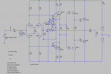
My design is attached.
It is already built and sounds really good.
Very detailed and controlled, with very, very low noise(read : Inaudible for all intents and purposes).
Hooked up both amp modules today for the first time, to some crappy gaming headphones from Sennheiser, but it sounds very promising.
Fully complementary floating JFET input stage biased at approx 3 mA per JFET, Darlington VAS'es, 2Sk1058/2SJ162 Lateral FET output stage biased at 180 mA per Lateral FET.
Gain is set at 2X.
The 100m output resistor is not included in my current test setup and is not really needed, unless you have to drive some seriously capacitive loads, then it would be wise to include it for stability reasons, but with normal headphone loads it is not needed.
DC coupled with a DC servo to keep the DC as clsoe to 0 as possible, testing shows the DC staying within a range of +/-1mV.
Attachments
Last edited:
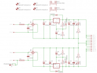
I also made a No-thump board with a time delay before activating the output relay and a fast off function that detects when the AC for the powersupply drops output. No more thumps/pops/plops when turning on or off your headamp.
Also made a simple supply board using LM317/LM337 regulstors, nothing special or highend but should work well, with a ripple of around 1mV P-P with the full bias on both channels. It is not some ultra low noise design but it should work very well. Currently using a lab supply to power both modules and that is quiet as a mouse.
Also made a simple supply board using LM317/LM337 regulstors, nothing special or highend but should work well, with a ripple of around 1mV P-P with the full bias on both channels. It is not some ultra low noise design but it should work very well. Currently using a lab supply to power both modules and that is quiet as a mouse.
Attachments

Last edited:
Nice, what made you go with fet input stage?
I just really, really like they way the complementary floating JFET input stage works. It is a simple ann elegant way to get a good sounding and very well behaving input stage that is totally symmetric.
Normally one would use the low-noise 2SK170/2SJ74 JFETs for such an input stage, but since the 2SJ74 has been discontinued for several years it is getting harder to get and rather expensive, especially as you need many for matching of the input stage JFETs. The 2SK246/2SJ103 JFETs are a decent alternative that performs almost as good. A bonus is that they are very cheap and easily available.
I have a question, why do you use a VBE multiplier for the biasing of the Lateral FET's, a fixed resistor will do just fine.
I used a pot to trim the bias on each module to around 180 mA bias and then I choose an resistor value as close to the value of the setting of the pot and mounted that into my modules, simple and effective. Ended up with 120 Ohm in the first module and then 97.6 Ohm in the second.
Bias is very stable, even after several hours of use it only swings +/- 5 mA from the 180 mA setting.
Class A affairs in general seem to be quite uncritical when it comes to biasing.
IMO the main reason for using a constant voltage source would be removing the coupling of idle currents in all stages.
BTW, are you sure that symmetric drain resistors in the input stage give best performance? Normally I'd think that R4/5 < R15/18 would result in better symmetry.
IMO the main reason for using a constant voltage source would be removing the coupling of idle currents in all stages.
BTW, are you sure that symmetric drain resistors in the input stage give best performance? Normally I'd think that R4/5 < R15/18 would result in better symmetry.
- Status
- This old topic is closed. If you want to reopen this topic, contact a moderator using the "Report Post" button.
- Home
- Amplifiers
- Headphone Systems
- Discrete, Class A Lateral MosFET Headphone amp (not another follower buffer!)