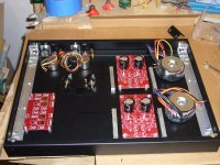
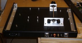
Well, this is where I'm at with this project now. It's a 1U rack box from Hammond that I've modified. I'm not happy with Hammond's quality but not sure anyone else is better. Holes don't line up, stuff like that. Hate it. I added the shiny aluminum angle strips on each side since Hammond didn't see fit to provide support there. Thank God for rivet nuts.
Anyway, the boards are from Jim's Audio. His LME49600 headphone amp, with two of his Kubota power supply regulators are included. Input will be switch selectable between balanced and unbalanced, with Jensen input transformers and dual wire wound pots for volume control. The pots will be controlled by a single shaft using miniature plastic roller chain with sprockets. It's all pretty simple really. The square bar stock is for heat sinks from TO-220 power transistors on the Kubota boards. Normal heat sinks are too tall, as are normal electrolytic capacitors. I had to get special short ones to fit in the 1U rack space.
Anyway, the boards are from Jim's Audio. His LME49600 headphone amp, with two of his Kubota power supply regulators are included. Input will be switch selectable between balanced and unbalanced, with Jensen input transformers and dual wire wound pots for volume control. The pots will be controlled by a single shaft using miniature plastic roller chain with sprockets. It's all pretty simple really. The square bar stock is for heat sinks from TO-220 power transistors on the Kubota boards. Normal heat sinks are too tall, as are normal electrolytic capacitors. I had to get special short ones to fit in the 1U rack space.
Attachments
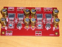
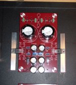
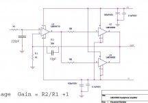
The amplifier board fully stuffed. The circuit has an LME49710 input and paralleled LME 49600 outputs per channel. I made some changes to the original circuit. I added a high frequency pole in the feedback loop as well as an RC low pass filter on the input.
Attachments
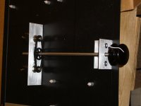
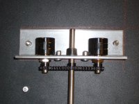
The volume control. Since I couldn't find any 2 gange wire wound potentiometers, I came up with this arrangement for controlling 2 pots with one shaft. Thanks to McMaster Carr for the parts.
Attachments
LUUUUV IT!!!
Thanks! I've never done this kind of project before. The chain is tight enough so that there's no slack and the two pots turn together. They have a linearity of +/-0.25% so if they are synchronized they should stay that way over the entire travel of the wiper.
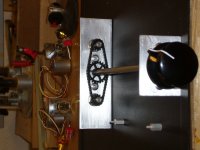
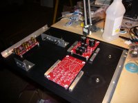
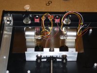
OK, more progress today. One Kubota regulator is stuffed, and 4 heatsinks are filed and sanded. The heatsinks are 3/8" square bar stock. One screw through the TO220 device and two up from the bottom on the back side of the panel to hold it in place. Time to drill and tap some holes.
The front support for the volume control shaft is finished as well.
Stuffing of second Kubota regulator is ongoing.
The front support for the volume control shaft is finished as well.
Stuffing of second Kubota regulator is ongoing.
Attachments
Good work there!
I like the use of the bar stock to connect to the bottom plate as one big heatsink...")
Thanks. The 1U rack height box is not tall enough for regular upright heatsinks so I had to come up with this solution. I need to buy the tap and drill though. It's going to be tricky I think drilling such small holes and then tapping them. I have a drill press now which makes this kind of work a lot easier.
why don't you try "the wire headphone amp" instead? their pcb are avaiable nowon, its better performance than this bad quality pcb
Of course, you realize it is rude to suggest something like this, don't you? Maybe you don't have proper manners. I was merely sharing my project, not asking for advice. If I was asking for advice, I would have clearly said so.
Unless you have seen this PCB in person I doubt you know what you're talking about. It is gold plated everywhere and the holes are through hole plated as well. This kind of chip amp is not rocket science anyway. Also, this circuit has two 49600's per channel, which is way overkill.
Exactly how is "the wire" a better PCB, or do you mean circuit?
Nice work. Great sense of detail for sure...
Thanks! It does take a lot of concentration for me to do this, and yet I'm still not satisfied. I'm waiting on some stuff that I ordered, as well as the time to proceed further.
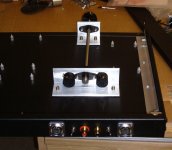
So, I had some time today and made some more progress on the enclosure. The rear panel is done. I installed the two Jensen transformers. I used a type of mu metal self stick thin metal under the transformers as a precaution. I put a larger sheet on the underside of the top panel (not pictured). The volume control is also done now. It works great. I need to lay out the front panel next, as well as drill and tap the 4 heatsinks. I finally got the 4-40 tap and drill set in the mail.
Thanks for the encouragement everyone!
Thanks for the encouragement everyone!
Attachments
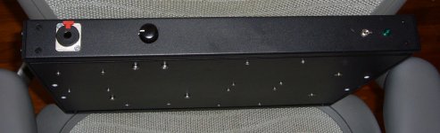
I finished the front panel today. I had a serious problem because I pressed too hard on the drill press and the drill bit grabbed the panel and bent it up. I was very upset! It took me a while to hammer it back into something close to the way it was before. Now I know - go easy on the drill press and let the bit take it's time to cut through the metal.
It's very industrial looking, I know, but it's all I'm really capable of right now in my shop with the tools that I have.
Thanks for looking.
It's very industrial looking, I know, but it's all I'm really capable of right now in my shop with the tools that I have.
Thanks for looking.
Attachments
Looks great and nothing wrong with the industrial look.
As for the grabbing bit, always clamp anything to the press table that you can, but I don't see much in the photo to complain about!
Oh, it was clamped to a piece of wood on the drill press, and both were clamped to that. That's why it surprised me. The drill bit just bent it right up! The paint job they used is pretty tough since I pounded the crap out of it to make it reasonably straight again and the paint only has a few scratches on it.
Thanks for your comments.
I added a high frequency pole in the feedback loop as well as an RC low pass filter on the input.
Would you mind elaborating on the above? Those ebay PCBs caught my eye & curious.
Nice looking project BTW... Combining the electrical & the mechanical (pot drive).
Would you mind elaborating on the above? Those ebay PCBs caught my eye & curious.
Nice looking project BTW... Combining the electrical & the mechanical (pot drive).
I replaced the 100K input resistor with a 220pF capacitor, and bypassed the 20kohm feedback resistor with a 10pF capacitor. Otherwise, this amplifier would be working out to radio frequencies. Since the input is connected to the wiper of a 10kohm potentiometer as a volume control, I didn't see the need for the 100k resistor. The LME49710 has an input bias current of a few nanoamps, so that tiny amount of DC through the pot hopefully won't make any difference.
The 10pF capacitor can be tack soldered on the backside of the board across the resistor.
I may not need the 220pF input capacitor since I'm using input transformers which limit input bandwidth anyway, but it's already soldered up now. I guess it's extra security.
Thanks!
Attachments
Last edited:
Great job, looks really good. Love the dual pot solution!
Thanks! I work on it when I have the time. There's always mistakes to either correct or accommodate... sigh.
- Status
- This old topic is closed. If you want to reopen this topic, contact a moderator using the "Report Post" button.
- Home
- Amplifiers
- Headphone Systems
- My Head Phone Amp Project