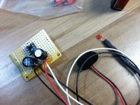
I'll post take some tonight which I'm working on the amp section. I hope my work isn't horrendous! The voltage all checked out and I don't see any bridges. I did put some jumpers is slightly the wrong spot and I'm trying to decide whether to work with it or try and get them out (the "S" or "M" jumpers on the sides, I'd angle everything if I leave them).
The only time solder work is horrendous is when it is a cold solder joint. Otherwise, it can only get better with experience. Finish this one and then decide if you need to make a second one to clean up the mistakes. This will give you two CMoy amps... maybe three if you are lucky.
It looks messier in the pic than I thought it looked in person. The Wimas are going to be a little tough to get in the right spot because the leads are so short. Maybe I ordered the wrong version.
Attachments
Looks better than my first CMOY did") .
.
I later learned that those Radioshack boards are hard to work with on the single holes because the pads are so small and easy to overheat. The dual strips in the middle is nice in some ways though.
Anyway, I'd run the Wima input caps parallel to the ground traces up by the power supply caps and use a resistor lead to connect the cap the the appropriate pin of the chip. That is a common method for making connections on perfboard. Fine solid copper wire works well also. Good technique is to solder on the components, then connect them using leads of the right length layed next to the two connections and use the iron melt the solder and push your connector piece in, applying a little more solder as necessary. I will also sometimes bend component leads over to accomplish the same thing if I can think far enough ahead.
Keep up the good work.
. I later learned that those Radioshack boards are hard to work with on the single holes because the pads are so small and easy to overheat. The dual strips in the middle is nice in some ways though.
Anyway, I'd run the Wima input caps parallel to the ground traces up by the power supply caps and use a resistor lead to connect the cap the the appropriate pin of the chip. That is a common method for making connections on perfboard. Fine solid copper wire works well also. Good technique is to solder on the components, then connect them using leads of the right length layed next to the two connections and use the iron melt the solder and push your connector piece in, applying a little more solder as necessary. I will also sometimes bend component leads over to accomplish the same thing if I can think far enough ahead.
Keep up the good work.
I'm getting too far ahead of myself but I just got my Skeleton DAC boards. It will take some courage to solder this DAC chip. I bought a couple boards for this reason though.
What amp should I think about making next? Maybe a Millet or something? I have my eye on some Fostex T50RP, and I read they need good solid amping.
What amp should I think about making next? Maybe a Millet or something? I have my eye on some Fostex T50RP, and I read they need good solid amping.
It looks messier in the pic than I thought it looked in person. The Wimas are going to be a little tough to get in the right spot because the leads are so short. Maybe I ordered the wrong version.
Looks better than some soldering jobs I have done on Light Sabres and remote controls. Like ddietz says, use copper wire to bridge the connections, I know I have liberally done that in the past.
Important thing is how it sounds, plus who knows how many times you will desolder and resolder it when you decide to change things around or reuse parts in new projects (seen some of the prices of real good capacitors? Makes sense when one costs need to be kept in line).
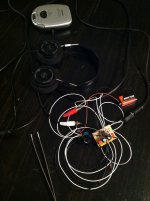
The hook-up wiring is a nasty mess. It will be nice to get this in an enclosure.
One question I have. What volume is ideal for digital sources? Turning my old CD player up to 10 and controlling the volume 100% with the amp was not good. The sound was badly broken up. Also the opposite, turning the CD player down to 2 was no good since I could hear some hiss from the amp up at top volume. So, I landed on about 7 for the CD player. That put listening level on the amp @ about 11 o'clock on the pot. Is that normal? Should the pot be able to crank up more?
One question I have. What volume is ideal for digital sources? Turning my old CD player up to 10 and controlling the volume 100% with the amp was not good. The sound was badly broken up. Also the opposite, turning the CD player down to 2 was no good since I could hear some hiss from the amp up at top volume. So, I landed on about 7 for the CD player. That put listening level on the amp @ about 11 o'clock on the pot. Is that normal? Should the pot be able to crank up more?
Attachments
The hook-up wiring is a nasty mess. It will be nice to get this in an enclosure.
One question I have. What volume is ideal for digital sources? Turning my old CD player up to 10 and controlling the volume 100% with the amp was not good. The sound was badly broken up. Also the opposite, turning the CD player down to 2 was no good since I could hear some hiss from the amp up at top volume. So, I landed on about 7 for the CD player. That put listening level on the amp @ about 11 o'clock on the pot. Is that normal? Should the pot be able to crank up more?
That is a lot of wire...
Your portable CD player output might be louder than what is "normal" (from listening to CD players, MiniDisc players, and iPod/MP# devices, I don't think that there is a set standard). Also, it might not be the cleanest signal depending on what circuitry they are running the music through.
Anyway, take the line out of a regular full size CD player that you would plug into an amp and hook it up with the RCA cables to the CMoy. From there, you can compare to your CD player. It might be more "standard" than a portable player.
Or lastly, get an iPod/iPhone and a line out from the bottom docking port into your CMoy.
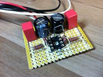
Wow, lead attaching was hard. But... it works!
I was nervous at first because it wasn't working. Then I realized I hadn't put the opamp in yet. LOL.
lol, been there.
Wow, lead attaching was hard. But... it works!
I was nervous at first because it wasn't working. Then I realized I hadn't put the opamp in yet. LOL.
Yes, the good old missing piece of the circuit -- still better than blue smoke (with me it is usually forgetting to turn the power bar on).
There might be a lot of things happening here at the same time. With the amp not encased and that much hook-up wire, you might be licking up noise from many areas. One cmoy I build had an annoying hum that I could not find until I accidentally held a mint tin over it. Turns out the hum was from the florescent light ballasts over my bench. In, out, and power wire sets should be twisted tightly together and kept separate from each other. They should be as short as possible.
100nF (.1uF) ceramic disks from each power pin to ground will help if the chip is oscillating. If it distorts at high volume that might be the/an issue. Solder the caps directly to the power pin on the bottom of the board. This is where your practice connecting with solid wire on the bottom will help.
Noise in the amp itself may also come from any wires run tightly on the bottom. You power wires, if tight to the board, may be adding noise. You want a few mm of space between the wire and any solder joints. Try touching/pressing on different parts of the board with no input connected.
Have you checked for DC offset on the outputs of the cmoy? What is the gain? Is there any DC at the chips input pins? More than a few mV at the output might be an issue?
Try a different source also as Broadcaster suggested. In general, portable MP3 players will be less noisy than cheap analog sources (walkman, etc), at least in my experience.
You should be doing this with cheap headphones (get a $3 pair at the dollar store) until you are confident that there will not be DC spikes, or accidental high output that could damage the phones. You want to check your DC at the output before connecting any phones.
Lastly, only a single 9V supply may be an issue to. If the CD player has a high output (which I bet it does), then only +_4vdc may not allow enough headroom to prevent the chip from clipping. You could try two 9V in series or high voltage DC wall supply. The OPAx132 series can handle up to +_18vdc. I personally can hear a difference in headroom using a 12vdc wall wart vs. a single 9vdc battery. For normal use with digital sources, a single 9v is fine, and much better than no amp at all.
Once you get this where your happy, try some different opamps. I personally prefer the OPA2228 over the 2134 and 2132 series
Last edited:
You might want to add a 100nF ceramic supply decoupling cap from each rail to ground. I don't see any in the pics.
I hadn't heard of this one yet. Any more info on this? I'm not familiar with what "rail" means yet. I followed this to a T, except that I used the Wima caps suggested and I did RCA ins rather than stereo.
How to Build the CMoy Pocket Amplifier
Can you link to the part you're talking about on Mouser? I'll need to put in another order soon do make the SkeletonDAC.
Should I boost up the gain resistor (R3) since I'm using Grados? Or just leave it in case I get a different set of headphones at some point? I have 1 kOhms in there now. I have a set of 2 kOhms I could swap in.
I'll shorten the wires when I get an enclosure lined up. Next time I need to get more wire colors too. All black and white is confusing.
A rail is the power supply lines. In this case you have a +4.5 and a -4.5 supply. Each of those is a "rail". Adding those caps should be done by connecting one leg of the cap directly to the chips (o sockets) pin and the other leg to ground. You want these as close as possible to the chip to prevent oscillation of the chip. This is very, very common with any chip used on hifi audio applications. You can also use ~10 uF electrolyics, but they are bigger and more expensive and not an improvement.
If I remember this circuit correctly, r3 at 1k means your gain is 11x. Gain = 1+ Rf/Rg. Using 2k for Rg may be more appropriate. Many people use gain of 2-6x. Someone else with experience will have to comment on what the grados need. Keep in mind you don't need to make the source much louder than the source is capable of. A little gain is helpful, but you don't need a lot. As you are finding, the source volume at 50-75% is likely idea performance wise for the source.
Your goal here is to add a little gain for less efficient and lower impedance (harder to drive) headphones while using the chip to "spread out the sound stage" and increase headroom to allow for a better sound. The amp's purpose here is really to condition or 'filter' the sound rather than amplifying the sound a lot as you would in order to drive speakers.
Old computer power supplies are a great source of free, multi-colored wire at a useful gauge
Last edited:
One cmoy I build had an annoying hum that I could not find until I accidentally held a mint tin over it. In, out, and power wire sets should be twisted tightly together and kept separate
So, I should encase the amp in metal? I was planning on a wood box, like the Grado amp.
100nF (.1uF) ceramic disks from each power pin to ground will help if the chip is oscillating.
I think I get this. It's what I measure between to get half the voltage +/-, right? This guy?
http://www.mouser.com/ProductDetail...=sGAEpiMZZMt1mVBmZSXTPPQUnq7ol7tGZljKIuTg6iI=
Have you checked for DC offset on the outputs of the cmoy
Ho do I test this?
What is the gain? Is there any DC at the chips input pins?
I have a 1 kOhm resistor on R3 (the tutorial site says that's gain "11").
Try a different source also as Broadcaster suggested.
I'll do that. I never use this CD player, I just wanted to test with something cheap.
You should be doing this with cheap headphones (get a $3 pair at the dollar store)
I'll have to get a converter to do this, or go get a 3.5mm jack. I didn't think ahead, and I couldn't wait, so I just tried with the Grados.
Lastly, only a single 9V supply may be an issue to.
I'll be doing this. I purchased enough rigging to wire in 2 batteries.
Last edited:
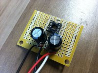
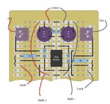
Here's how I ended up laying out the board to accommodate the Wima caps. hopefully this is not causing me any problems.
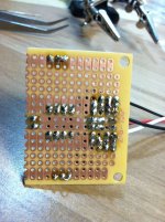
All the ins and outs I went through the hole in the board. For all grounds I soldered wire right to the bottom of the board (under the opamp). Not through a hole just right onto the copper strip.
All the ins and outs I went through the hole in the board. For all grounds I soldered wire right to the bottom of the board (under the opamp). Not through a hole just right onto the copper strip.
Attachments
Last edited:
So, I should encase the amp in metal? I was planning on a wood box, like the Grado amp.
I only say it might be an issue. If it is, you could line to top (and maybe bottom) of the box with aluminum or copper foil. Cooking Al foil should be fine, or you can use the Al tape made for HVAC duct work
I think I get this. It's what I measure between to get half the voltage +/-, right? This guy?
140-50U5-104M-RC Xicon Ceramic Disc Capacitors
It is the + or - voltage you get when you probe from pin 4 and 8 to the virtual ground. That capacitor linked looks fine, but seems rather expensive to me. I'f think they should only be a few cents a most. That seems to be the cheapest mouser carries though
I like this better0.1uF 50V Ceramic Disc Capacitor
To test for DC offset, simply set your meter to mV DC and measure from one output to ground with the amp on. You can can try it with and without an input going. With the DC blocking caps (1uF Wima's) the source's DC will be blocked because the capacitors do not allow DC voltage to pass. Still, testing also with the source present may be important as if the source is driving the chip to oscillate, more DC may be present at the output. You want to check these things in all situations, IMO. DC into your headphones or a speaker is bad as it can damage the speaker. IT can also distort the signal and lower sound quality. There is a critical amount though. I'd expect to see up to a few 10's of mV in this amp and that is not an issue. Check both left and right to ground separately.
I'll have to get a converter to do this, or go get a 3.5mm jack. I didn't think ahead, and I couldn't wait, so I just tried with the Grados.
You could always add both types, just don't try to use both at once.
I purchased enough rigging to wire in 2 batteries.
Is this intended to be a desktop amp or the portable kind you carry around in your pocket? If desktop, I'd skip the batteries entirely or add the ability to also use a wall wart DC supply. You can probably find a used one laying around somewhere for nothing. Anything up to ~36vdc and more than a few 100ma would run this fine.
The position of the Wima caps is fine.
The routing of the power wires is over complicated in my opinion. They run over the board and signal traces essentially twice. I'd attach the battery leads at the top, first row, in the first holes after the 3x group where the led is. Make the wire a little long, and bend it over and solder to connect to the 3x pads. Remove the metal power jumpers from the bottom of the board and move the loose wires directly to the chip power pin pads. I've always run those loosely on the bottom side.
The jumpers from the input caps to the input pads are unnecessarily long. They could act as antennas. Move the caps right up against R4 and jumper the connection on the bottom.
- Status
- This old topic is closed. If you want to reopen this topic, contact a moderator using the "Report Post" button.
- Home
- Amplifiers
- Headphone Systems
- CMOY newb