Hi guys, I've build 1 cmoy last week but encountering distOrtion issue after power on for few seconds.
NJM4562
100k input res
0.47uf input cap
3.3k res feedback loop
1k res R3
NO R5
Power Supply:
Single 9v batt
Dual 330uF elec cap
0.1uF bypass cap
I din use any pot or switch since it is still on the breadboard.
I try every method I found with Google but still the same....
Chnaged new batt. Added R5. Switch OPamp to 2134. Change input cap to 0.1.
Nothing works!!! help please
Sorry for bad english
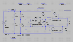
Did you make the power supply like in figure 3 here, with the two capacitors in series and the two 4.7k resistors across the capacitors?
HeadWize - Project: A Pocket Headphone Amplifier by Chu Moy
The "+4.5V" from that diagram should be going to pin 8 of the NJM4562 or OPA2134, the "-4.5V" going to pin 4, and the middle "ground" connects to one side of R2 and R3 as in figure 1.
What brand and model number of headphone or IEM are you using?
The NJM4562 probably isn't the best chip to be using since it has a minimum supply voltage of +/-4.0Vdc and you will only get +/-4.5Vdc from your power supply. And that is with a fresh battery - it will drop of course as your battery runs down. Your OPA2134 would be a better choice with its minimum supply voltage of +/-2.5Vdc. That gives you a lot more supply voltage headroom as the battery wears down.")
Also, you probably already know, but if you are using pins 2 and 3 for the input then pin 1 is the output, not pin 6 as on the original diagram.
HeadWize - Project: A Pocket Headphone Amplifier by Chu Moy
The "+4.5V" from that diagram should be going to pin 8 of the NJM4562 or OPA2134, the "-4.5V" going to pin 4, and the middle "ground" connects to one side of R2 and R3 as in figure 1.
What brand and model number of headphone or IEM are you using?
The NJM4562 probably isn't the best chip to be using since it has a minimum supply voltage of +/-4.0Vdc and you will only get +/-4.5Vdc from your power supply. And that is with a fresh battery - it will drop of course as your battery runs down. Your OPA2134 would be a better choice with its minimum supply voltage of +/-2.5Vdc. That gives you a lot more supply voltage headroom as the battery wears down.
Also, you probably already know, but if you are using pins 2 and 3 for the input then pin 1 is the output, not pin 6 as on the original diagram.
Last edited:
None. I skip the 4.7k res. Other 2 of my cmoy works normally with skipping it.
Tried 2134. Same result. Distortion comes after power on for few seconds. The cmoy works and sounds normal only for a few seconds....
Every pins are connected accurately. I am very sure that none of then has been mixed up.
Ya. Since it is dual channel
Tried 2134. Same result. Distortion comes after power on for few seconds. The cmoy works and sounds normal only for a few seconds....
Every pins are connected accurately. I am very sure that none of then has been mixed up.
Ya. Since it is dual channel
Did you make the power supply like in figure 3 here, with the two capacitors in series and the two 4.7k resistors across the capacitors?
HeadWize - Project: A Pocket Headphone Amplifier by Chu Moy
The "+4.5V" from that diagram should be going to pin 8 of the NJM4562 or OPA2134, the "-4.5V" going to pin 4, and the middle "ground" connects to one side of R2 and R3 as in figure 1.
What brand and model number of headphone or IEM are you using?
The NJM4562 probably isn't the best chip to be using since it has a minimum supply voltage of +/-4.0Vdc and you will only get +/-4.5Vdc from your power supply. And that is with a fresh battery - it will drop of course as your battery runs down. Your OPA2134 would be a better choice with its minimum supply voltage of +/-2.5Vdc. That gives you a lot more supply voltage headroom as the battery wears down.
Also, you probably already know, but if you are using pins 2 and 3 for the input then pin 1 is the output, not pin 6 as on the original diagram.
None. I skip the 4.7k res. Other 2 of my cmoy works normally with skipping it.
You might try putting those 2 4.7k resistors in on this one and see if it solves the problem. Those resistors prevent the two series capacitors from charging unequally and developing different DC voltages across them. Usually they can't be skipped. The resistors are what is setting your DC point at 1/2 of the 9V, while the two capacitors are just acting as AC bypasses around the resistors for the signal current. The op amp also needs a DC path back to ground for the input bias current via R2 and R3, which capacitors alone for the power supply would block.
What may be happening is after a couple of seconds one of the series capacitors charges more than the other and your "ground" winds up off the target by a few volts in one direction or the other, which will move your output DC bias off center (away from 1/2 supply) causing the output waveform to clip on one rail or the other.
The series capacitors in your other two amps likely were just well matched, by chance. If by luck the two capacitors are very well matched the center point will be around 1/2 of the supply initally, but it won't be nearly as stable with load as with the two series resistors included. In your other two amps the small amount of leakage current through the electrolytic capacitors may be what is supplying the DC input bias current needs for the op amp. Here is another article about it, the second section on "resistor divider":
http://tangentsoft.net/elec/vgrounds.html
Last edited:
I would recommend leaving the 4.7k's in there, even if they are not causing the distortion problem. You will get better results in the end.
I've been thinking of getting a pair of D2000s or D5000s! Nice phones. Unfortunately the 25 ohm impedance on those may not work that well with a CMOY. Chu Moy gets into that down in that "appendix 1" section of the main article. His fixes for that issue, the "load resistor", is really just limiting the available output volume and potentially affects the frequency response a bit. Low impedance headphones will cause the output DC bias point to shift when that simple virtual ground power supply gets unbalanced, which in turn will put DC across your headphones.
For nice headphones like your D2000s you might want to just give up on the CMOY and look at something like an O2 headphone amp in one of the threads here
http://www.diyaudio.com/forums/headphone-systems/193977-objective2-o2-headphone-amp-diy-project.html
NwAvGuy: O2 Details
That one does have the necessary current output to drive your 25R headphones. The fellow who designed it even has published measured results into low impedance headphones. There is a fellow in Germany who is selling kits of parts worldwide in the group buy thread here
http://www.diyaudio.com/forums/group-buys/201323-o2-amplifier-kit-pcb-groupbuy-worldwide.html
And a fellow in England who ran the last group buy is selling a completed amplfier, along with a fellow in Canada I believe. They have posts in that forum too.
Anyway, back on your distortion problem with this CMOY. At this point if it were me I would test each and every part (resistor and capacitor) with a multimeter to make sure the value is what I'm expecting, or alternatively substitute in another similar part. Could you post a photograph of your build? Maybe I or someone else here can spot something.
Some voltage readings would also help, if you have a meter. Measure from ground to each of pins 1, 2, 3, 4, and 8 on the op amp.
Last edited:
Planned to Build an O2 and MiniMax soon. My currect project is with the Cmoy with EQ. So i started on a breadboard. But this distortion pops up before the equilizer circuit, which is too bad.
The breadboard is damn messy. I guess i am the only 1 who can read it. LOL.
Get u update for the Voltage from each pin once i reach home.
The breadboard is damn messy. I guess i am the only 1 who can read it. LOL.
Get u update for the Voltage from each pin once i reach home.
I would recommend leaving the 4.7k's in there, even if they are not causing the distortion problem. You will get better results in the end.
I've been thinking of getting a pair of D2000s or D5000s! Nice phones. Unfortunately the 25 ohm impedance on those may not work that well with a CMOY. Chu Moy gets into that down in that "appendix 1" section of the main article. His fixes for that issue, the "load resistor", is really just limiting the available output volume and potentially affects the frequency response a bit. Low impedance headphones will cause the output DC bias point to shift when that simple virtual ground power supply gets unbalanced, which in turn will put DC across your headphones.
For nice headphones like your D2000s you might want to just give up on the CMOY and look at something like an O2 headphone amp in one of the threads here
http://www.diyaudio.com/forums/headphone-systems/193977-objective2-o2-headphone-amp-diy-project.html
NwAvGuy: O2 Details
That one does have the necessary current output to drive your 25R headphones. The fellow who designed it even has published measured results into low impedance headphones. There is a fellow in Germany who is selling kits of parts worldwide in the group buy thread here
http://www.diyaudio.com/forums/group-buys/201323-o2-amplifier-kit-pcb-groupbuy-worldwide.html
And a fellow in England who ran the last group buy is selling a completed amplfier, along with a fellow in Canada I believe. They have posts in that forum too.
Anyway, back on your distortion problem with this CMOY. At this point if it were me I would test each and every part (resistor and capacitor) with a multimeter to make sure the value is what I'm expecting, or alternatively substitute in another similar part. Could you post a photograph of your build? Maybe I or someone else here can spot something.
Some voltage readings would also help, if you have a meter. Measure from ground to each of pins 1, 2, 3, 4, and 8 on the op amp.
Here is where those voltages should sit. All taken with the amp input connected to ground, the headphone plugged in, and into the 3+ seconds after the distortion starts.
ground to pin 1 = 0Vdc
ground to pin 2 = 0Vdc
ground to pin 3 = 0Vdc
ground to pin 4 = -4.5Vdc
ground to pin 8 = +4.5Vdc
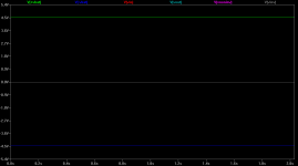
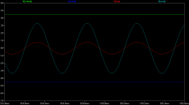
The first sim plot below is with 0V signal in, the second with 1Vpeak in.
ground to pin 1 = 0Vdc
ground to pin 2 = 0Vdc
ground to pin 3 = 0Vdc
ground to pin 4 = -4.5Vdc
ground to pin 8 = +4.5Vdc
The first sim plot below is with 0V signal in, the second with 1Vpeak in.
Attachments
Last edited:
Here is where those voltages should sit. All taken with the amp input connected to ground, the headphone plugged in, and into the 3+ seconds after the distortion starts.
ground to pin 1 = 0Vdc
ground to pin 2 = 0Vdc
ground to pin 3 = 0Vdc
ground to pin 4 = -4.5Vdc
ground to pin 8 = +4.5Vdc
The first sim plot below is with 0V signal in, the second with 1Vpeak in.[/QUOTE
without headphone
8.19V batt
1=191.6mV
2=17.5mV
3=17.3mV
4=3.94V
5=17.4mV
6=17.3mV
7=190.8mV
8=3.75V
with Denon D2000
8.03V batt
1=15.3
2=1.4
3=11.4
4=6.96
5=11.4
6=1.4
7=15.3
8=0.79v
Last edited:
Yep, there is one of the problems. That simple CMOY just isn't going to work with those low impedance 25R D2000 headphones. Your measurements show how badly that big current load is unbalancing the simple voltage divider power supply.
With no headphone load the supply balance is not bad, +3.75V on pin 8 and -3.94V on pin 4. With with that 25 ohm load they are so unbalanced they are almost at the power supply rails. Worse still your DC on the output (pin 1) goes from 200mV up to 15V - that is enough to damage headphones if left for an extended period.
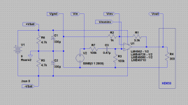
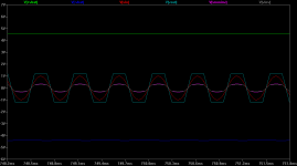
Here it is in a simulation. The sim I did previously was for the 300 ohm HD650s which is within the range of what the CMOY can handle. Now below is what happens with the 25 ohm D2000s. Not good. Your real-life circuit numbers were even much worse. With the 1Vpeak input signal the result is severe clipping along with the DC offset.
So - don't use your D2000s with the CMOY! stick with your higher impedance HD650s. See if you get the distortion on those with the 4.7k power supply resistors in place. It is also entirely possible that DC offset has damaged your D2000s. You should try them with another known-good output source and see if they are still OK.
A "safe" way to run things would be put a 1000uf - 2200uF electrolytic capacitor between the output of the op amp and your headphones, at least until the build is worked out, to block DC.
EDIT: I just added the actual OPA2134 simulation model, which is now the 3rd plot. I had been doing these with a LME49720 which is similar. The results are similar, heavy clipping into a 25R load.
Also, check the connection on those two 4.7K resistors you added. The 4th plot is the 25R phones with zero input which show slightly unbalanced power supply rails, but the 5th and 6th plot are what happens with the 25R phones without the 4.7K resistors. Massively unbalanced rails, with numbers that seem to match the kind of thing you are getting. The op amp input bias (DC) current has nowhere to go and the offset voltage gets extreme.
With no headphone load the supply balance is not bad, +3.75V on pin 8 and -3.94V on pin 4. With with that 25 ohm load they are so unbalanced they are almost at the power supply rails. Worse still your DC on the output (pin 1) goes from 200mV up to 15V - that is enough to damage headphones if left for an extended period.
Here it is in a simulation. The sim I did previously was for the 300 ohm HD650s which is within the range of what the CMOY can handle. Now below is what happens with the 25 ohm D2000s.
Not good. Your real-life circuit numbers were even much worse. With the 1Vpeak input signal the result is severe clipping along with the DC offset.So - don't use your D2000s with the CMOY! stick with your higher impedance HD650s. See if you get the distortion on those with the 4.7k power supply resistors in place. It is also entirely possible that DC offset has damaged your D2000s. You should try them with another known-good output source and see if they are still OK.
A "safe" way to run things would be put a 1000uf - 2200uF electrolytic capacitor between the output of the op amp and your headphones, at least until the build is worked out, to block DC.
EDIT: I just added the actual OPA2134 simulation model, which is now the 3rd plot. I had been doing these with a LME49720 which is similar. The results are similar, heavy clipping into a 25R load.
Also, check the connection on those two 4.7K resistors you added. The 4th plot is the 25R phones with zero input which show slightly unbalanced power supply rails, but the 5th and 6th plot are what happens with the 25R phones without the 4.7K resistors. Massively unbalanced rails, with numbers that seem to match the kind of thing you are getting. The op amp input bias (DC) current has nowhere to go and the offset voltage gets extreme.
Attachments
-
 CMOY circuit 25R phones.png38.3 KB · Views: 240
 -
 CMOY 9V batt 1Vpeak_in.25R headphones.png21.1 KB · Views: 240
 -
 CMOY 9V batt 1Vpeak_in.25R phones OPA2134.png21.2 KB · Views: 219
 -
 CMOY 9V batt 0Vpeak_in.25R phones.png15 KB · Views: 214
 -
 CMOY circuit 25R no 4.7k.png33.9 KB · Views: 211
 -
 CMOY 25R no 4.7K.png14.6 KB · Views: 57
Last edited:
I guess something goes wrong with the virtual ground itself. Everything sounds normal if i unplug both input and output GND from the breadboard.
I tried TLE2426. But weird. It wont split the voltage all.
I did a simple test on that.
9V+ ==> IN
9V- ==> COMMON (mid pin)
GnD ==> OUT
GnD to V+ = 400++mV
Gnd to V- = 200++mV
Izzit possible that i burn my TLE2426?
I tried TLE2426. But weird. It wont split the voltage all.
I did a simple test on that.
9V+ ==> IN
9V- ==> COMMON (mid pin)
GnD ==> OUT
GnD to V+ = 400++mV
Gnd to V- = 200++mV
Izzit possible that i burn my TLE2426?
I agree, it does sound like your virtual ground is the problem. A TLE2426 would be a good way to go. They can source or sink up to 20mA. With your HD650 300 ohm headphones the maximum current, including the op amp quiescent current, should be somewhere around 18mA.
It sounds like your TLE2426 is hooked up right, so it probably is bad.
It sounds like your TLE2426 is hooked up right, so it probably is bad.
I have had a similar problem with a cMoy in the past, the problem you describe is a typical case for a faulty OPAMP. Try changing the OPAMP and see if you have the same issue.
I personally use OPA2227, it is a good OPAMP and suits my sound preference and I have never had any issues with them.
I personally use OPA2227, it is a good OPAMP and suits my sound preference and I have never had any issues with them.
I agree, it does sound like your virtual ground is the problem. A TLE2426 would be a good way to go. They can source or sink up to 20mA. With your HD650 300 ohm headphones the maximum current, including the op amp quiescent current, should be somewhere around 18mA.
It sounds like your TLE2426 is hooked up right, so it probably is bad.
I solved the problem after I change inPut res from 100k to 10k.
And of course, with 4.7k resistor split is on the board.
DC offset went below 5mV for both L And R.
But it is impossible to replace the 100k input res to 10k as the high pass filter function gone. Damn fed up to stabilize those bipolar opamp
Hey that good news! 5mV is excellent for an offset. You are quite right, the NJM4562 is bipolar input with a max bias current of 500nA, while the OPA2134 is FET with 100pA max bias current. I had missed that. That is the problem and your resistor change is the solution. I also just noticed that the NJM chip is frequency compensated for closed loop gains over 10, while the OPA2134 is unity gain (1x) stable.
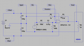
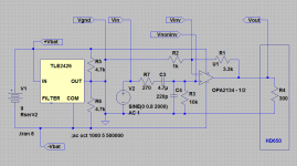
Try adding the RF filter that NwAvGuy used on the O2, a 270 ohm resistor in series with the input and a 220pF ceramic capacitor to ground following it. That will give you an RF filter with a corner frequency of around 2.1mHz, high enough that the gain roll-of won't affect the audio band. The attentuation of the input signal would be minimal with a 270R / 10K voltage divider. Also consider replacing that 0.47 coupling cap with a 2.2uf - 4.7uf metalized film, like this one to solve that high pass filter problem.
MKS2B044701K00KSSD WIMA Polyester Film Capacitors
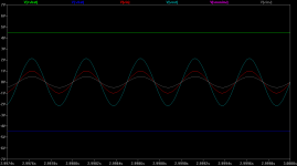
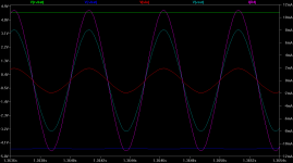
The results look pretty good, below! The magenta is the current through the 300 ohm headphones with the scale on the right. The others are voltage with the scale on the left.
Attachments
Last edited:
Hey that good news! 5mV is excellent for an offset. You are quite right, the NJM4562 is bipolar input with a max bias current of 500nA, while the OPA2134 is FET with 100pA max bias current. I had missed that. That is the problem and your resistor change is the solution. I also just noticed that the NJM chip is frequency compensated for closed loop gains over 10, while the OPA2134 is unity gain (1x) stable.
Try adding the RF filter that NwAvGuy used on the O2, a 270 ohm resistor in series with the input and a 220pF ceramic capacitor to ground following it. That will give you an RF filter with a corner frequency of around 2.1mHz, high enough that the gain roll-of won't affect the audio band. The attentuation of the input signal would be minimal with a 270R / 10K voltage divider. Also consider replacing that 0.47 coupling cap with a 2.2uf - 4.7uf metalized film, like this one to solve that high pass filter problem.
MKS2B044701K00KSSD WIMA Polyester Film Capacitors
The results look pretty good, below! The magenta is the current through the 300 ohm headphones with the scale on the right. The others are voltage with the scale on the left.
Aghhh~ Not Possible to try this schematic out until i get those TLE2426 and come res @ local shop.
Now i have a new problem with my current setup.
Power Supply (Normal Resistor Divider)
330uF X2
4.7k ohm X2
Amp Circuit
0.47uF input cap
10k ohm input res
1k ohm R3
2k ohm R4
no R5
DC Offset (without input and output) : 1.3mV L || 1.4mV R
DC Offset (with input and Apple Earpiece - After distortion) : 4.8mV L || 5.1mV R
Even which such low offset. Distortion is there once i crack up my volume from my iPhone.. But weird.. Those reading i get from the meter still below the par.
Tried to add 150 ohm @ R5
Decoupling with 0.1uF
No luck at all.
I have had a similar problem with a cMoy in the past, the problem you describe is a typical case for a faulty OPAMP. Try changing the OPAMP and see if you have the same issue.
I personally use OPA2227, it is a good OPAMP and suits my sound preference and I have never had any issues with them.
Sorry bro, I missed ur post. LOL
I guess the issue i m facing now is how to tweak my current circuit to "SUIT" my NJM4562.
Sound wise. Personally i prefer 2228 and 8397.
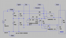
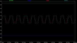
Maybe I found the problem. I added the simulation model for the NJM4562. Looks like the NJM4562 can't handle nearly the amount of output current that the OPA2134 can, if the sim model is anywhere near reality.
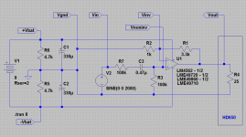
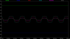
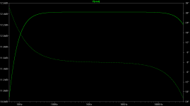
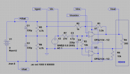
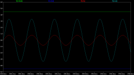
I've changed the virtual ground back to just the 4.7Ks and the 330uFs. The first plot is a 300 ohm headphone load with the OPA2134. Looks good. The second plot is the NJM4562 with exactly the same components - only change is the chip. Clips badly into 300 ohm, meaning not enough current output capability. Finally the last plot is the NJM4562 into a 3K load, just to test lower current requirements, and it works fine.
The second half of each chip is just wired up an a unity gain buffer to get it out of the way in the simulation.
So... try swapping chips. If your NJM4562 sounds distorted but your OPA2134 doesn't, with no other circuit changes, that confirms the sim results. Leaving out the 270R resistor and 220pF cap for the RF filter and using the 0.47uF coupling cap instead of teh 3.7uF doesn't make any significant difference at the 2kHz in the simulation, so you can just use the parts you have on hand. The bigger coupling cap only affects the low end below 100Hz or so, of course.
I added the simulation model for the NJM4562. Looks like the NJM4562 can't handle nearly the amount of output current that the OPA2134 can, if the sim model is anywhere near reality. I've changed the virtual ground back to just the 4.7Ks and the 330uFs. The first plot is a 300 ohm headphone load with the OPA2134. Looks good. The second plot is the NJM4562 with exactly the same components - only change is the chip. Clips badly into 300 ohm, meaning not enough current output capability. Finally the last plot is the NJM4562 into a 3K load, just to test lower current requirements, and it works fine.
The second half of each chip is just wired up an a unity gain buffer to get it out of the way in the simulation.
So... try swapping chips. If your NJM4562 sounds distorted but your OPA2134 doesn't, with no other circuit changes, that confirms the sim results. Leaving out the 270R resistor and 220pF cap for the RF filter and using the 0.47uF coupling cap instead of teh 3.7uF doesn't make any significant difference at the 2kHz in the simulation, so you can just use the parts you have on hand. The bigger coupling cap only affects the low end below 100Hz or so, of course.
Attachments
-
 CMOY OPA2134 0.8Vpk in 300R out circuit.png40.2 KB · Views: 45
 -
 CMOY OPA2134 0.8Vpk in 300R out.png21.7 KB · Views: 38
 -
 CMOY NJM4562 0.8Vpk in 300R out circuit.png39.8 KB · Views: 38
 -
 CMOY NJM4562 0.8Vpk in 300R out.png18.2 KB · Views: 36
 -
 CMOY NJM4562 0.8Vpk in 3k out circuit.png41.2 KB · Views: 39
 -
 CMOY NJM4562 0.8Vpk in 3k out.png21.4 KB · Views: 45
Last edited:
I have totally no idea how to use LTSPICE. Cant even add batt symbols. LOL
BTW. i added bass boost circuit within the feedback loop and after R4. 0.22uF + 4.7k res
Distortion still remain...
Until i double up my supply to 18v.... I just noticed that 4562 minimum voltage = 5V!!!!
BTW. i added bass boost circuit within the feedback loop and after R4. 0.22uF + 4.7k res
Distortion still remain...
Until i double up my supply to 18v.... I just noticed that 4562 minimum voltage = 5V!!!!
- Status
- This old topic is closed. If you want to reopen this topic, contact a moderator using the "Report Post" button.
- Home
- Amplifiers
- Headphone Systems
- Cmoy distortion after 3sec