O2 headphone amp 8 & 12 AAA 1000mAh NiMh mod
Here is a mod idea I'm going to toss out but not build myself right now - no need for a long runtime portable - so it might work or it might fail miserably on actual build. Builder beware - untested!
I know some folks are looking at a B3 box build from the front panel group-buy B3 panel orders, so here is yet another thing you might be able to do with your O2 in a B3 box instead of the standard B2 box.
http://www.boxenclosures.com/technical_drawings/B3-080.pdf
From the mechanical drawings it appears that two of these 6-cell AAA battery holders
12BH463-GR Eagle Plastic Devices Battery Holders, Snaps & Contacts
for 6 AAA NiMH 1000mAh cells
MAHA / POWEREX 1000mAh AAA NiMH Rechargeable Batteries 2pcs Pack
would fit in a B3 box if turned sideways and the O2 PCB notched out under the two 9V batteries. There appears to be nothing under the batteries on the PCB but their 3 wires back to B+, B- (at the battery diodes) and ground anyway, although the notch would come close to at least one signal trace it looks like.
These holders have wire leads attached. Keep in mind that the B3 box is tall enough that a do-it-yourself piece of perfboard can be slid into the top slot in front, above the O2 board, and used for connections. The wire leads could be attached to the top board to route them nicely from the battery holders down to the battery diodes in back, where the notched-out PCB traces went.
The net result is for each 6 cell NiMH battery pack is 7.2V, one cell less than the O2 standard 8-cell 8.4V Tenergy "9V" 250mAh battery, so you would loose a little voltage on each rail (6 x 1.2V/cell = 7.2V) but gain 1000mAh vs. 250, a 4x increase in run time!
The charging resistors would be changed to 620R at 1/2W to maintain a constant end of charge trickle charge at 5mA. Maha tells me that 5mA is the recomended continuous trickle for their 9.6V cell. The AAA may be higher - something to check. [ 11.8V - 1.42/cell(charged) ] * 6cells / 620R = 5.3mA.
Good luck if anyone tries to build it! The result would be an O2 that is 0.6 inches taller, but the same in the other dimensions, with about 4 times the runtime.
Here is a mod idea I'm going to toss out but not build myself right now - no need for a long runtime portable - so it might work or it might fail miserably on actual build.
Builder beware - untested!I know some folks are looking at a B3 box build from the front panel group-buy B3 panel orders, so here is yet another thing you might be able to do with your O2 in a B3 box instead of the standard B2 box.
http://www.boxenclosures.com/technical_drawings/B3-080.pdf
From the mechanical drawings it appears that two of these 6-cell AAA battery holders
12BH463-GR Eagle Plastic Devices Battery Holders, Snaps & Contacts
for 6 AAA NiMH 1000mAh cells
MAHA / POWEREX 1000mAh AAA NiMH Rechargeable Batteries 2pcs Pack
would fit in a B3 box if turned sideways and the O2 PCB notched out under the two 9V batteries. There appears to be nothing under the batteries on the PCB but their 3 wires back to B+, B- (at the battery diodes) and ground anyway, although the notch would come close to at least one signal trace it looks like.
These holders have wire leads attached. Keep in mind that the B3 box is tall enough that a do-it-yourself piece of perfboard can be slid into the top slot in front, above the O2 board, and used for connections. The wire leads could be attached to the top board to route them nicely from the battery holders down to the battery diodes in back, where the notched-out PCB traces went.
The net result is for each 6 cell NiMH battery pack is 7.2V, one cell less than the O2 standard 8-cell 8.4V Tenergy "9V" 250mAh battery, so you would loose a little voltage on each rail (6 x 1.2V/cell = 7.2V) but gain 1000mAh vs. 250, a 4x increase in run time!
The charging resistors would be changed to 620R at 1/2W to maintain a constant end of charge trickle charge at 5mA. Maha tells me that 5mA is the recomended continuous trickle for their 9.6V cell. The AAA may be higher - something to check. [ 11.8V - 1.42/cell(charged) ] * 6cells / 620R = 5.3mA.
Good luck if anyone tries to build it! The result would be an O2 that is 0.6 inches taller, but the same in the other dimensions, with about 4 times the runtime.
Last edited:
A couple of more random thoughts on the mod 12-cell AAA NiMh mod, then I'll shut up.
* The common wires connecting the two battery packs should be star grounded, exactly like RocketScientist has done with the PC traces currently under the batteries (that would get notched out), by running them both back to the ground plane by the battery diodes and making the connection there, rather than right at the battery packs.
* The result would be heavy with 12 AAA NiMH cells! At about 15g each that is 0.6lbs just for the batteries. Not so good for carrying around unless in a backpack.
* If a slide-in proto board is used in the top slot of the B3 box, above the O2 board in the bottom slot, it may be possible to have enough space to add NiMH fast-charge battery charge management chips on that board. Many of the 6-cell controller chips use switchmode, unfortunately, which may generate audio band noise. But it appears some like this one can also be wired to work in linear mode
DS2715Z+ Maxim Integrated Products Battery Management
DS2715 NiMH Battery Pack Charge Controller - Overview
http://datasheets.maxim-ic.com/en/ds/DS2715.pdf
Figure 6 in the data sheet gives the linear controller schematic. One chip and associated circuitry per battery pack. The controllers use a thermistor on the battery pack to calculate dT/dt for the fast charge part of the cycle, then trickle charge after that. The benefit here would be reduced charge time.
A proto board in the top slot of the B3 chasis would need to be notched out around the battery packs just like the main PCB in the bottom slot. But the section in back that butts up against the back panel could actually be used to run things through the back panel plate like "charging" LEDs from the battery charge controller chips, a "charging" switch, etc.
* With the battery-powered rails reduced to +/-7.2Vdc nominal with the packs, the new maximum amp clipping voltage would be around 3.8Vrms, down from the 4.5Vrms with the 8.4V cells. With a gain stage of 2.5 that would be a max input of 3.8Vrms / 2.5 = 1.52Vrms. With this mod it may be good to chose a gain ratio like 1x/2.5x or 1.5x/3x if the intended source has a higher output voltage.
Last edited:
notching the O2 headphone amp PCB for AAA cell packs
I figured that I would give the notched-PCB mod I posted last November, above, a try. I'm going to build up a low(er) voltage unity gain version of the O2 with 4x the run-time of a standard O2 headphone amp using two 6-cell 1000mAhr NiMH battery packs.
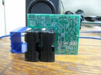
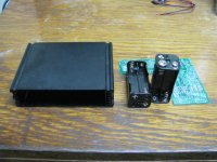
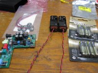
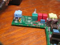
The first photo shows a new O2 PCB (this one happens to be from JDS Labs), two 6-cell AAA battery holders with snap connections from Mouser
12BH463B-GR Eagle Plastic Devices | Mouser
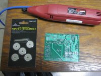
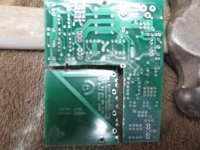
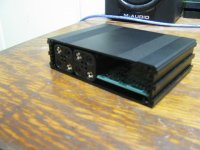
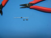
and a B3-080 chassis from Allied. In the post above I gave a link for the same AAA pack at Mouser with wire leads coming out. That works too, but I figured that I would go with snaps to remove the packs easily if I want. The next photo shows why the O2 PCB has to be notched. The 6 cell AAA holder is just a bit too tall to fit in the B3-080 box sitting on top of the PCB board. The next photo shows what is going to happen to the PCB. A high speed hobby tool with a diamond cutting wheel.
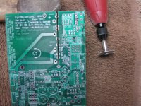
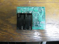
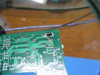
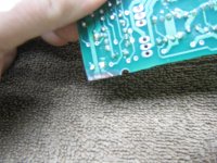
The first cut in the next photo is right through the middle of all the O2's battery terminal pads, which makes lining up the cut super easy. I just free-handed the cut. It literally feels like cutting through soft butter, not very difficult. Note in this photo you can see the two large PCB traces on the top of the cut-out section that go from one terminal of each battery to connect together on the trace that goes under R2 to form ground. This is where the same two wire leads from the new battery packs should connect too also, forming a star ground.
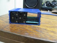
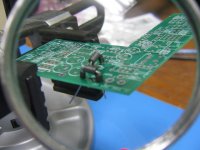
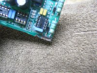
The next photo shows the other side of the cut-out section. Here you can see the B+ and B- traces and where those two wires from the battery packs will need to connect. The notched out section only removed these power and ground traces going from the batteries. No signal lines needed to be cut!
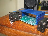
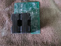
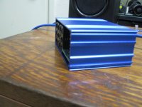
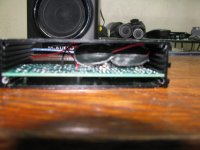
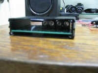
The next two photos show how the 6 cell AAA packs fit right into the new notch. The final 3 photos show how the whole thing fits just perfectly into the B3-030 chassis.
The new 6 cell packs will be around 1.45Vdc x 6 = 8.70Vdc when full charged and around 0.9Vdc x 6 = 5.40Vdc when discharged, at the time the power management circuit should kick in to disconnect. To make the O2 work with the new slightly lower battery voltage the following in the O2 would have to be changed:
* R1 and R2 changed to hit a C/40 or C/30 trickle charge endpoint. AAA NiMH cells seem to be available in capacities (C) of around 700mAhr to 1000mAhr.
* R9 changed to make the power management circuit turn off at 0.9V x 6 x 2 rails = 10.8Vdc.
Everything else stays the same in the O2 amp. The chips are all rated to work OK at the minimum voltage +/-5.4Vdc power rails. The output voltage swing will be +/-1.2Vdc less of course, but the runtime will increase over the 250mAhr "8.4Vdc" cells by 2.8x (700mAhr NiMH AAA's) up to 4x (1000mAhr NiMH AAA's). If a standard O2 amp will run for around 8 hours on the two "8.4Vdc" NiMH batteries, that means increasing the run-time to 22 - 32 hours with these "7.2Vdc" nominal AAA cell packs!
I figured that I would give the notched-PCB mod I posted last November, above, a try. I'm going to build up a low(er) voltage unity gain version of the O2 with 4x the run-time of a standard O2 headphone amp using two 6-cell 1000mAhr NiMH battery packs.
The first photo shows a new O2 PCB (this one happens to be from JDS Labs), two 6-cell AAA battery holders with snap connections from Mouser
12BH463B-GR Eagle Plastic Devices | Mouser
and a B3-080 chassis from Allied. In the post above I gave a link for the same AAA pack at Mouser with wire leads coming out. That works too, but I figured that I would go with snaps to remove the packs easily if I want. The next photo shows why the O2 PCB has to be notched. The 6 cell AAA holder is just a bit too tall to fit in the B3-080 box sitting on top of the PCB board. The next photo shows what is going to happen to the PCB.
A high speed hobby tool with a diamond cutting wheel. The first cut in the next photo is right through the middle of all the O2's battery terminal pads, which makes lining up the cut super easy. I just free-handed the cut. It literally feels like cutting through soft butter, not very difficult. Note in this photo you can see the two large PCB traces on the top of the cut-out section that go from one terminal of each battery to connect together on the trace that goes under R2 to form ground. This is where the same two wire leads from the new battery packs should connect too also, forming a star ground.
The next photo shows the other side of the cut-out section. Here you can see the B+ and B- traces and where those two wires from the battery packs will need to connect. The notched out section only removed these power and ground traces going from the batteries. No signal lines needed to be cut!
The next two photos show how the 6 cell AAA packs fit right into the new notch. The final 3 photos show how the whole thing fits just perfectly into the B3-030 chassis.
The new 6 cell packs will be around 1.45Vdc x 6 = 8.70Vdc when full charged and around 0.9Vdc x 6 = 5.40Vdc when discharged, at the time the power management circuit should kick in to disconnect. To make the O2 work with the new slightly lower battery voltage the following in the O2 would have to be changed:
* R1 and R2 changed to hit a C/40 or C/30 trickle charge endpoint. AAA NiMH cells seem to be available in capacities (C) of around 700mAhr to 1000mAhr.
* R9 changed to make the power management circuit turn off at 0.9V x 6 x 2 rails = 10.8Vdc.
Everything else stays the same in the O2 amp. The chips are all rated to work OK at the minimum voltage +/-5.4Vdc power rails. The output voltage swing will be +/-1.2Vdc less of course, but the runtime will increase over the 250mAhr "8.4Vdc" cells by 2.8x (700mAhr NiMH AAA's) up to 4x (1000mAhr NiMH AAA's). If a standard O2 amp will run for around 8 hours on the two "8.4Vdc" NiMH batteries, that means increasing the run-time to 22 - 32 hours with these "7.2Vdc" nominal AAA cell packs!
Attachments
-
 IMG_1675.JPG173.9 KB · Views: 367
 -
 IMG_1669.JPG185.7 KB · Views: 363
 -
 IMG_1676.JPG208.7 KB · Views: 355
 -
 IMG_1677.JPG238.1 KB · Views: 355
 -
 IMG_1679.JPG172.3 KB · Views: 345
 -
 IMG_1681.JPG213.8 KB · Views: 89
 -
 IMG_1682.JPG224.8 KB · Views: 100
 -
 IMG_1686.JPG160.7 KB · Views: 96
 -
 IMG_1685.JPG161.8 KB · Views: 96
 -
 IMG_1684.JPG175.2 KB · Views: 106
Last edited:
notched O2 headphone amp PCB with B2-080 and 4xAAA
Here is something else that can be done with the notched-out O2 headphone amp PCB that I just posted above. Turns out that two 4-cell AAA battery packs will fit fine in the notch in a standard B2-080 chassis!
4 AAA NiMH cells lowers the nominal rail voltage to 1.2Vdc x 4 = 4.8Vdc each, reducing the maximum voltage swing on the output by at least 3.6Vdc, so this version is best suited to high-sensitivity low-impedance headphones that don't require a large voltage swing.
The first photo shows the B2-080 case (from Allied), battery holders (from Mouser), and notched PCB, same one as in the post above. I again used the battery holders with snaps so I could use them with wire-lead snap connectors for easy removal. But Mouser also has the version that just has wire leads coming out that can be soldered right to the PCB. Here is the Mouser part:
http://www.mouser.com/ProductDetail/Eagle-Plastic-Devices/12BH443B-GR/?qs=%2fha2pyFaduhzLyBTuuav3fDSqvHW%2ffl452QsSgmJ5%252b%2ftJ2u9lZbPKQ%3d%3d
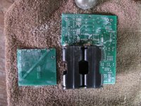
The next photo shows how the two 4-cell AAA holders fit into the notched-out battery area on the PCB. This is the same notch I cut in the post above for the 6 cell holders, so the notch is a little bit wider than needed for the 4 cell holders as can be seen on the right side.
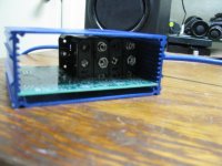
The next two photos show the whole assembly in the B2-080 case. Perfect fit! The final photo shows the wire lead battery snaps attached to the batteries. Each pair of two wires should be twisted together, then those bundles run on top of the batteries (there is room between the batteries and the top of the case for this) to the PCB trace connection points.
Making the 4 cell NiMH battery packs work with the O2 is similar to the above post for 6 cell packs, same three changes (R1, R2, & R9), but with two additional twists. The U1 NJM2068 chip is only rated down to +/-4Vdc rails, which isn't enough for the lowest battery-cutoff level of 0.9Vdc x 4 = +/-3.6Vdc. U1 would have to be replaced with a LME49720 chip which is rated down to +/- 2.5Vdc power rails. RocketScientist reviewed the LM49720 in his blog posts, as I recall, and it was at least at good as the NJM2068 in all areas (better in several). The only problem he noted was the cost - $2.50 vs. 0.50 for the NJM2068. The other difference is the voltage regulators have to be reduced to 9Vdc to make the O2's battery trickle charge resistor scheme work right - LM7809 and LM7909. That gives "on AC" power rails in this one of +/-9Vdc with nominal "on batteries" rails of +/-4.8Vdc.
Here is something else that can be done with the notched-out O2 headphone amp PCB that I just posted above. Turns out that two 4-cell AAA battery packs will fit fine in the notch in a standard B2-080 chassis!
4 AAA NiMH cells lowers the nominal rail voltage to 1.2Vdc x 4 = 4.8Vdc each, reducing the maximum voltage swing on the output by at least 3.6Vdc, so this version is best suited to high-sensitivity low-impedance headphones that don't require a large voltage swing.
The first photo shows the B2-080 case (from Allied), battery holders (from Mouser), and notched PCB, same one as in the post above. I again used the battery holders with snaps so I could use them with wire-lead snap connectors for easy removal. But Mouser also has the version that just has wire leads coming out that can be soldered right to the PCB. Here is the Mouser part:
http://www.mouser.com/ProductDetail/Eagle-Plastic-Devices/12BH443B-GR/?qs=%2fha2pyFaduhzLyBTuuav3fDSqvHW%2ffl452QsSgmJ5%252b%2ftJ2u9lZbPKQ%3d%3d
The next photo shows how the two 4-cell AAA holders fit into the notched-out battery area on the PCB. This is the same notch I cut in the post above for the 6 cell holders, so the notch is a little bit wider than needed for the 4 cell holders as can be seen on the right side.
The next two photos show the whole assembly in the B2-080 case. Perfect fit! The final photo shows the wire lead battery snaps attached to the batteries. Each pair of two wires should be twisted together, then those bundles run on top of the batteries (there is room between the batteries and the top of the case for this) to the PCB trace connection points.
Making the 4 cell NiMH battery packs work with the O2 is similar to the above post for 6 cell packs, same three changes (R1, R2, & R9), but with two additional twists. The U1 NJM2068 chip is only rated down to +/-4Vdc rails, which isn't enough for the lowest battery-cutoff level of 0.9Vdc x 4 = +/-3.6Vdc. U1 would have to be replaced with a LME49720 chip which is rated down to +/- 2.5Vdc power rails. RocketScientist reviewed the LM49720 in his blog posts, as I recall, and it was at least at good as the NJM2068 in all areas (better in several). The only problem he noted was the cost - $2.50 vs. 0.50 for the NJM2068.
The other difference is the voltage regulators have to be reduced to 9Vdc to make the O2's battery trickle charge resistor scheme work right - LM7809 and LM7909. That gives "on AC" power rails in this one of +/-9Vdc with nominal "on batteries" rails of +/-4.8Vdc.Attachments
Last edited:
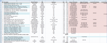
O2 amp 2x4 AAA +/-8Vdc power supply measurements
I decided to build up the 2 x 4-cell AAA NiMh RocketScientist O2 headphone amp in the B2-080 case, with the notched PCB above, rather than the 2 x 6-cell verson. None of my headphones need more than a couple of volts of output swing, so may as well go with the smaller B2 chassis. The DIY buildup of the 2 x 6-cell AAA NiMH version would be similar.
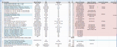
Attached is a modified version of RocketScientist's O2 BOM with the new/changed parts in blue if anyone else should want to try this DIY build. I wound up placing the order with Digikey because Mouser does not have 9VAC transformers. But I've included Mouser and some Farnell and RS Components crosses too.
Details...
Turns out +/-8V rails and regulators are a better choice than +/-9V, as I wrote above. Drops the voltage overhead to the NiMH cells to 2.0Vdc, same as the standard O2, which allows for the same trickle charge scheme. On the regulator input end the lower regulator voltage provides an extra volt of regulator overhead which, along with 1000uF caps and schottky rectifier diodes, allow just a 9VAC transformer to be used.
Since the 9Vac transformers have unloaded voltage of around 12vac - 13Vac, the highest peak voltage will be around 18V. That allows the filter capacitors to be dropped down to 25V from 35V, which in turn permits the capacitance to be increased to 1000uF each from 470uF in the standard O2. The higher cap in turn decreases the ripple voltage and increases the minimum voltage going into the regulator, preserving the data sheet recommended 2.5Vdc drop across the regulators.
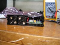
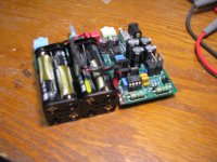
To help reduce conducted EMI (cell phone radiation coming in on the power cable) and nuke line transients I've added ferrite beads to the rectifier diodes, which are now schottky to save 0.4V drop each. I've put a 28.6Vdc breakdown bidirectional Transorb (TVS) diode across the power input jack under the PCB (across the transformer secondary).
The battery manufacturer says continuous trickle charging of 10mA -30mA is OK for the AAA NiMh cells. I've picked 26mA, giving a value for R1 and R2 of [(8Vdc - 0.2Vdc schottky) - (4 cells x 1.45Vdc charge endpoint)] / 26mA = 75R. These are specified at 2W to cover the case where one AAA battery pack completely shorts out leaving 8V across the resistor.
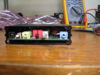
The first two photos shows how the ferrite beads on the revised BOM are placed on the schottky recifiers diodes. BTW, this good idea is not mine! I learned about this from a DIY amp in another forum. The diodes are now mounted on end (tombstoned) with the beads on the flying lead. A 1-40mHz bead is stacked with a 40-200mHz bead to form a wideband filter, as per a JW Miller app note. The 200mHz bead is longer and is best placed on the top.
The next photo shows the TVS diode from the BOM soldered across the DC input jack. I bent the diode leads around the pins first, before soldering. Helps to solder the unused 3rd lead on the jack first to hold the jack, then solder the other two. The diode is bidirectional, so there is no "right way" or banded end.
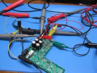
The next photo shows the test setup. I'm only building up and testing the AC power supply section now. Turns out every resistor in the power management circuit has to change to work correctly with the lower rail voltage. All those values are in the revised BOM and will be tested later. It is hard to see from the photo, but the "battery end" of R1 and R2 (now 75R) are grounded with test clips to supply a [(8V - 0.2V) / 75R] = 100mA load on each power supply rail. Dead batteries being charged will be about 50mA, the chip quiescent current with NJM4556s are about 22mA, and the headphone load is expected to be up to 25mA, for a total of about 100mA. Hence the 100mA dummy test load.
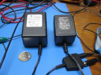
The next photo shows two 9Vac transformers being tested. The bigger one is the 9Vac 1A unit on the BOM. The smaller is a 9Vac 400mA sourced locally. Digikey has a 9Vac 500mA unit for just 70 cents less. I picked 1A to cover maximum secondary current de-rating for the half wave rectifiers, as per a Hammond rectifier app note.
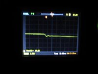
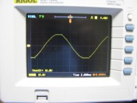
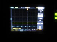
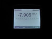
The next two photos show the negative rail scope traces for the MC7908 regulator output (yellow) and input (blue) for the smaller transformer, along with a DMM reading on the regulator output voltage. Minimum output voltage below the ripple with the 100mA load is about -11.7Vdc, leaving -11.7V - (-7.9V) = -3..8Vdc minimum across the regulator. The data sheet makes a big deal about maintaining 2.5Vdc across the regulators, even though their dropout at that low current is about 1Vdc. The incoming ripple with the two 1000uF caps is just -0.7Vdc from the scope trace. The positive rail readings are not shown but similar.
The next photo is the scope trace with the larger 9Vac 1A transformer. Note the output voltage (yellow) is the same, as it should be, but the minimum input voltage is now up to -13.9Vdc and the ripple has increased to -0.75Vdc. The power dissipation in the regulator though is still just (14 - 8) * 0.1A = 0.6 = 600mW, hardly enough to even make the regulator tabs slightly warm.
Given these readings a 12Vac transformer could also be used. The power dissipation in the regulators would go up to around 1.2W each.
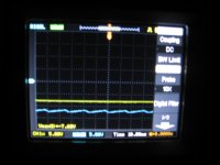
The final two photos are about the issue of diode and transformer secondary ringing (snubbers) given that the rectifier diodes have changed to schottky. In the first scope photo you can see the slight drop at the top/bottom of each waveform, on the rightmost portion, where the diodes turn off and ringing occurs. The final photo zooms in on the ringing to show about 7uS period (150kHz) and about three cycles before being fully damped out. From Hagerman's snubber paper the goal of a parallel C + R snubber is to damp out the ring in 2-3 cycles. The goal of just a parallel capacitor is to shift the ringing to a lower frequency (than 500kHz in his paper). Since both are already true here, no snubbers are required.
I decided to build up the 2 x 4-cell AAA NiMh RocketScientist O2 headphone amp in the B2-080 case, with the notched PCB above, rather than the 2 x 6-cell verson. None of my headphones need more than a couple of volts of output swing, so may as well go with the smaller B2 chassis. The DIY buildup of the 2 x 6-cell AAA NiMH version would be similar.
Attached is a modified version of RocketScientist's O2 BOM with the new/changed parts in blue if anyone else should want to try this DIY build. I wound up placing the order with Digikey because Mouser does not have 9VAC transformers. But I've included Mouser and some Farnell and RS Components crosses too.
Details...
Turns out +/-8V rails and regulators are a better choice than +/-9V, as I wrote above. Drops the voltage overhead to the NiMH cells to 2.0Vdc, same as the standard O2, which allows for the same trickle charge scheme. On the regulator input end the lower regulator voltage provides an extra volt of regulator overhead which, along with 1000uF caps and schottky rectifier diodes, allow just a 9VAC transformer to be used.
Since the 9Vac transformers have unloaded voltage of around 12vac - 13Vac, the highest peak voltage will be around 18V. That allows the filter capacitors to be dropped down to 25V from 35V, which in turn permits the capacitance to be increased to 1000uF each from 470uF in the standard O2. The higher cap in turn decreases the ripple voltage and increases the minimum voltage going into the regulator, preserving the data sheet recommended 2.5Vdc drop across the regulators.
To help reduce conducted EMI (cell phone radiation coming in on the power cable) and nuke line transients I've added ferrite beads to the rectifier diodes, which are now schottky to save 0.4V drop each. I've put a 28.6Vdc breakdown bidirectional Transorb (TVS) diode across the power input jack under the PCB (across the transformer secondary).
The battery manufacturer says continuous trickle charging of 10mA -30mA is OK for the AAA NiMh cells. I've picked 26mA, giving a value for R1 and R2 of [(8Vdc - 0.2Vdc schottky) - (4 cells x 1.45Vdc charge endpoint)] / 26mA = 75R. These are specified at 2W to cover the case where one AAA battery pack completely shorts out leaving 8V across the resistor.
The first two photos shows how the ferrite beads on the revised BOM are placed on the schottky recifiers diodes. BTW, this good idea is not mine! I learned about this from a DIY amp in another forum. The diodes are now mounted on end (tombstoned) with the beads on the flying lead. A 1-40mHz bead is stacked with a 40-200mHz bead to form a wideband filter, as per a JW Miller app note. The 200mHz bead is longer and is best placed on the top.
The next photo shows the TVS diode from the BOM soldered across the DC input jack. I bent the diode leads around the pins first, before soldering. Helps to solder the unused 3rd lead on the jack first to hold the jack, then solder the other two. The diode is bidirectional, so there is no "right way" or banded end.
The next photo shows the test setup. I'm only building up and testing the AC power supply section now. Turns out every resistor in the power management circuit has to change to work correctly with the lower rail voltage. All those values are in the revised BOM and will be tested later. It is hard to see from the photo, but the "battery end" of R1 and R2 (now 75R) are grounded with test clips to supply a [(8V - 0.2V) / 75R] = 100mA load on each power supply rail. Dead batteries being charged will be about 50mA, the chip quiescent current with NJM4556s are about 22mA, and the headphone load is expected to be up to 25mA, for a total of about 100mA. Hence the 100mA dummy test load.
The next photo shows two 9Vac transformers being tested. The bigger one is the 9Vac 1A unit on the BOM. The smaller is a 9Vac 400mA sourced locally. Digikey has a 9Vac 500mA unit for just 70 cents less. I picked 1A to cover maximum secondary current de-rating for the half wave rectifiers, as per a Hammond rectifier app note.
The next two photos show the negative rail scope traces for the MC7908 regulator output (yellow) and input (blue) for the smaller transformer, along with a DMM reading on the regulator output voltage. Minimum output voltage below the ripple with the 100mA load is about -11.7Vdc, leaving -11.7V - (-7.9V) = -3..8Vdc minimum across the regulator. The data sheet makes a big deal about maintaining 2.5Vdc across the regulators, even though their dropout at that low current is about 1Vdc. The incoming ripple with the two 1000uF caps is just -0.7Vdc from the scope trace. The positive rail readings are not shown but similar.
The next photo is the scope trace with the larger 9Vac 1A transformer. Note the output voltage (yellow) is the same, as it should be, but the minimum input voltage is now up to -13.9Vdc and the ripple has increased to -0.75Vdc. The power dissipation in the regulator though is still just (14 - 8) * 0.1A = 0.6 = 600mW, hardly enough to even make the regulator tabs slightly warm.
Given these readings a 12Vac transformer could also be used. The power dissipation in the regulators would go up to around 1.2W each.
The final two photos are about the issue of diode and transformer secondary ringing (snubbers) given that the rectifier diodes have changed to schottky. In the first scope photo you can see the slight drop at the top/bottom of each waveform, on the rightmost portion, where the diodes turn off and ringing occurs. The final photo zooms in on the ringing to show about 7uS period (150kHz) and about three cycles before being fully damped out. From Hagerman's snubber paper the goal of a parallel C + R snubber is to damp out the ring in 2-3 cycles. The goal of just a parallel capacitor is to shift the ringing to a lower frequency (than 500kHz in his paper). Since both are already true here, no snubbers are required.
Attachments
-
 IMG_1726.JPG82.4 KB · Views: 46
 -
 IMG_1725.JPG103.5 KB · Views: 55
 -
 IMG_1721.JPG97.3 KB · Views: 40
 -
 IMG_1723.JPG61 KB · Views: 51
 -
 IMG_1718.JPG108.1 KB · Views: 59
 -
 IMG_1724.JPG174.3 KB · Views: 69
 -
 IMG_1710.JPG151.5 KB · Views: 62
 -
 IMG_1708.JPG148.7 KB · Views: 64
 -
 IMG_1706.JPG103.6 KB · Views: 65
 -
 Capture.PNG148.2 KB · Views: 44
Last edited:
8-cell AAA O2 amp, unity gain, build-up part 1
Here is the rest of the build-up of a 8-cell AAA RocketScientist O2 headphone amp with unity gain (no U1).
First a couple of corrections from above. First photo below is the missing test setup. I ran out of photo attachment slots on the post. The other is the datasheet recommended drop across the voltage regulators is 3.5Vdc, not 2.5, and the dropout is 2Vdc and not 1V.
The next two photos show the PCB edges for the battery connections buffed down to the copper on both sides of the board with a wire wheel on a hobby tool. These are the traces that used to come from the battery connectors on the O2 PCB that were sliced when the board was cut. Here you just buff up the edges and solder the wires from the batteries right back on.
To wire the O2 for unity gain with U1 left off the board - input signal fed directly to the pot - the following parts are left off the board: R14, R16, R17, R19, R20, R21, R22, R23, S2, C19, C20. The PCB holes for U1 pins 1 and 3 are jumped, then 5 and 7 are jumpered.
The next photo shows the jumped U1 pins and all the parts above that are left off. The remaining resistors and caps in the input section photo are R3, R7, C11, and C12.
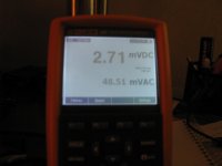
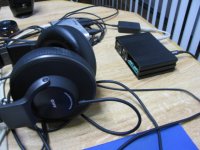
The next photo shows the DMM results with the amp running off the +/-8Vdc AC rails with a 32R AKG K550. About 3mV of DC offset, same as the standard O2 amp of course, and normal listing levels of about 50mV (rms).
The next photos show the battery holder and clip preparation. The center-wire 9V battery clips from Mouser point the wires down toward the PCB when attached, unfortunately. To solve that I cut off the ABS cover on the clips to allow the wires to go up and over the battery holders. Then twisted the leads and heat shrink tubing applied. Route the battery wire bundle over the top of the batteries and the down the right side to mate with the PCB edge contacts.
The two wires for "ground" are then soldered to the PCB edge pads on the top, with the positive and negative leads soldered to the pads on the bottom. The wires run down through the half-hole left from the PCB cutting.
The next two photos show how the finished battery holders + batteries fit into the B2-080 case.
The final photo is the finished modified amp, running on the 8 NiMH AAA cells and unity gain with no U1 chip (no NJM2068). Works great! From the simulations and sine wave scope shots that I'll post later, the maximum output swing into 32R is about 1V rms just before the (dead) batteries cut off by the power management circuit. Way more swing than is needed for the K550s at 50mV rms. On AC with the +/-8Vdc rails it will swing about 4V rms.
Here is the rest of the build-up of a 8-cell AAA RocketScientist O2 headphone amp with unity gain (no U1).
First a couple of corrections from above. First photo below is the missing test setup. I ran out of photo attachment slots on the post. The other is the datasheet recommended drop across the voltage regulators is 3.5Vdc, not 2.5, and the dropout is 2Vdc and not 1V.
The next two photos show the PCB edges for the battery connections buffed down to the copper on both sides of the board with a wire wheel on a hobby tool. These are the traces that used to come from the battery connectors on the O2 PCB that were sliced when the board was cut. Here you just buff up the edges and solder the wires from the batteries right back on.
To wire the O2 for unity gain with U1 left off the board - input signal fed directly to the pot - the following parts are left off the board: R14, R16, R17, R19, R20, R21, R22, R23, S2, C19, C20. The PCB holes for U1 pins 1 and 3 are jumped, then 5 and 7 are jumpered.
The next photo shows the jumped U1 pins and all the parts above that are left off. The remaining resistors and caps in the input section photo are R3, R7, C11, and C12.
The next photo shows the DMM results with the amp running off the +/-8Vdc AC rails with a 32R AKG K550. About 3mV of DC offset, same as the standard O2 amp of course, and normal listing levels of about 50mV (rms).
The next photos show the battery holder and clip preparation. The center-wire 9V battery clips from Mouser point the wires down toward the PCB when attached, unfortunately. To solve that I cut off the ABS cover on the clips to allow the wires to go up and over the battery holders. Then twisted the leads and heat shrink tubing applied. Route the battery wire bundle over the top of the batteries and the down the right side to mate with the PCB edge contacts.
The two wires for "ground" are then soldered to the PCB edge pads on the top, with the positive and negative leads soldered to the pads on the bottom. The wires run down through the half-hole left from the PCB cutting.
The next two photos show how the finished battery holders + batteries fit into the B2-080 case.
The final photo is the finished modified amp, running on the 8 NiMH AAA cells and unity gain with no U1 chip (no NJM2068). Works great!
From the simulations and sine wave scope shots that I'll post later, the maximum output swing into 32R is about 1V rms just before the (dead) batteries cut off by the power management circuit. Way more swing than is needed for the K550s at 50mV rms. On AC with the +/-8Vdc rails it will swing about 4V rms.Attachments
-
 IMG_1752.JPG154.3 KB · Views: 74
 -
 IMG_1751.JPG181.2 KB · Views: 74
 -
 IMG_1749.JPG212.7 KB · Views: 63
 -
 IMG_1746.JPG95.3 KB · Views: 60
 -
 IMG_1736.JPG180.9 KB · Views: 54
 -
 IMG_1731.JPG182.9 KB · Views: 44
 -
 IMG_1730.JPG209.1 KB · Views: 52
 -
 IMG_1712.JPG190.2 KB · Views: 48
 -
 IMG_1753.JPG151.6 KB · Views: 66
 -
 IMG_1754.JPG173.6 KB · Views: 67
Last edited:
8-cell AAA O2 amp, unity gain, build-up part 2
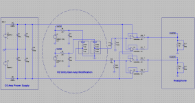
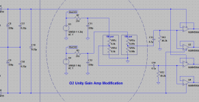
Below are attached the circuit diagram the input stage RocketScientist's O2 reduces to when the parts listed above are left off and the U1 part of the PCB is jumpered across. The input signal is applied directly across the pot (unity gain).
Although there is no gain, there is attentuation with the pot, which is what my sources require. I also left (and socketed) R3 and R7 which can be increased for further attentuation, to regain more range on the pot for higher voltage sources.
With the first stage U1 op amp gone the only clipping that can occur now is in the output stage, of course. C13 and C14 are still in place for DC blocking in both directions.
A revised version of RocketScientist's BOM is attached for the build. I made one change in a power management resistor from the BOM posted earlier. All the changed/added parts from RocketScientist's standard BOM are in blue.
Attachments
Last edited:
O2 amp 8x 10440 lithium cell +/-18Vdc higher voltage mod
Here is yet another DIY thing that can be done with a RocketScientist O2 headphone amp PC board with the battery section notched out, as above, and two of the 4 cell AAA battery holders. This modification produces an O2 with +/-18Vdc AC power rails and +/-14.8Vdc nominal rails on batteries, which in turn would increase the output voltage swing before clipping to around 10.5Vdc peak, 3.5Vdc higher than the standard O2 headphone amp.
This modification is only for use with higher impedance (250R - 600R) headphones. As RocketScientist has pointed out the higher voltage rails would cause too much power dissipation in the U3 and U4 output chips with lower impedances (higher currents).
I'm not going to build up this particular modification since I have no need for a higher voltage O2, so builder beware! I may have some mistakes in here that will need to be worked out.
"10440" size lithium ion cells are the same size as AAA cell and would fit right in the battery holder. Lithium cells are not safe to trickle charge, unlike NiMH, but it turns out that 4 cell lithium charger boards with charge management controller ICs are available on eBay for just $6 USD:
3 or 4 Cell Li ion Lithium 18650 Battery Input Ouput Protection PCB 4 5A Charge | eBay
The boards are small enough they could easily be mounted over the battery holders in a taller B3-080 case, by attaching them to a perboard slid into the upper slot in the case. One charge controller board for each 4 cell battery holder. The eBay boards make use the the Seiko S8254 lithium charge controller chip:
Overview - Battery Protection IC for 3-Serial or 4-Serial-Cell Pack S-8254A series
http://datasheet.sii-ic.com/en/battery_protection/S8254A_E.pdf
with solder pads on the bottom of the PCB. The charge controller works like a "balance charger" by attaching to the connection point between every battery to measure each battery's voltage in the series chain. All those connection points are available at the two ends of the battery holders.
Resistors R1 and R2 would need to be left off the O2 PCB. The input voltage for each charge controller board is taken between the AC power supply side of the O2 PCB R1 or R2 holes and ground as appropriate. The voltage regulator chips would change to +/-18Vdc MC7818 and MC7918. Diodes D1 and D5 should be changed to 1N4002 silicon diodes so the extra voltage drop insures the rail voltages will be less than the +/-18Vdc maximum for the chips, even if the regulators are at their +0.3Vdc higher end of the regulation curve (+/-18.3Vdc).
A 16Vac transformer would be (barely) adequate if the input diodes D3 and D4 are changed to Schottky for lower voltage drop, as above with the 8 cell AAA mod, and the filter capacitors are changed to (taller) 820uF 35Vdc units for lower ripple. Mouser part 667-EEU-FR1V821L are still 10mm diameter like the standard O2 filter caps, but 25mm tall which fit just fine in the taller B3-080 case. In fact, they still leave space for a PC board to be slid in the upper case slot. A 18Vac or 20Vac transformer would leave more margin for low AC line voltage and voltage fluctuations.
The power supply will (still) automatically switch between AC, battery, and battery charging by the action of diodes D1, D2, D5, and D6. When the AC section is plugged into the transformer diodes D1 and D5 (now 1N4002) output +/-18Vdc -0.7Vdc = +/-17.3Vdc to the rest of the O2 circuitry and to the lithium charging boards wired in where R1 and R2 used to connect.
The regulation tollerance on the voltage regulators give a range of about +/-17.0Vdc to +/-17.6Vdc, all (barely) under the +/-18Vdc maximum of U1 - U4. As RocketScientist has noted before, running the chips that close to maximum may eventually result in some failures. If the headphone impedance is 300R or 600R, with lower current requirements, +/-22Vdc LME49860 chips could be used for U1, U3 and U4 to provide some extra rail voltage margin. The LME49860 is just the higher voltage version of the LME49720.
The 10440 cells should still be the "protected" variety, with onboard chips to monitor current draw, voltage, and polarity such as these:
TrustFire 10440 600mAh 3.7V AAA Li-Ion PROTECTED Battery
even though a "balance" charge controller chip is being used. The reason is for the discharge situation, where the charge controller will be off and the series string of 10440 cells would be acting without any external management.
With the O2 on AC the +/-17.3 out of D1 and D5 would reverse bias D2 and D6 leaving them "off" and the batteries cut off from the circuit, since the battery voltage will nominally be 3.7 * 4 = 14.8Vdc and fully charged 4.2 * 4 = 16.8Vdc. This means the charge controller boards will be able to charge the batteries without the O2 circuitry trying to tag along as a load on the batts.
When the AC transformer is unplugged, D1 and D5 drop to zero and turn off, cutting off the voltage to the charge controller boards and turning on D2 and D6 to power the O2 circuits from batteries.
All of the resistors in the O2 power management circuit would have to be adjusted, again, for the higher voltage rails like I did above with the (lower voltage) 8 cell NiMH O2. I've written enough about the math of that circuit here and in the mod thread that the calculations are left as an exercise for the reader.
Resistors would have to be soldered across C16 and C21 on the back of the PCB to form voltage dividers with R8 and R24 to keep the gate voltages of the mosfets below the 30Vdc maximum given the new maximum 35.2Vdc rail-to-rail voltage. For example, with R8 = R24 = 270K, 82K resistors would do the job and limit the gate voltages to 27Vdc.
Last edited:
Any ideas for adding upc1237 for DC protection?
Any ideas for adding upc1237 for DC protection? I'm not sure if +ve thresh hold 0.7V & -ve threshold of -0.2V would be of any use in h/p as its basically a spk. protection IC or will it require some sort of DC instrumentation amp (to amplify few mV DC offset to couple of V for upc1237 to detect).
Ragards,
availlyrics
- Status
- This old topic is closed. If you want to reopen this topic, contact a moderator using the "Report Post" button.
- Home
- Amplifiers
- Headphone Systems
- O2 amp 12 AAA 1000mAh NiMh mod