This is my first junkbox attempt at composite amps, and any feedback is greatly appreciated.

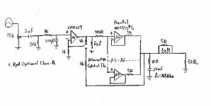
Pot is intentionally placed before coupling caps so that if any DC develops at the source, I'd know that there is a fault.
OPA2227 was chosen for to its automatic input bias current cancellation, relatively low GBW, and good phase margin.
I happened to have enough NE5532 to make a poweramp, so naturally this is the buffer of choise. With 4x gain at the global feedback loop, it should slow the effective bandwidth at OPA2227 down to 2Mhz, although I am not certain whether a 2Mhz - 10Mhz difference is a good enough safety margin.
Likewise, I've considered parallel OPA2604 on the output, being 20Mhz GBW these should make a good candidate but at increased cost. Douglas Self wasn't too thrilled about these, but I have a few lying around and they shouldn't be too bad inside the feedback loop. If all else fails, OPA2227 will have to operate on local feedback.
Current sharing resistors are at 5 ohms, but these could probably go down to 1 ohm in practice.
Now a couple of questions.
Is a single 100 Ohm resistor be good enough at isolating the gain stage & buffers? I recall seeing a design utilizing isolating resistors before every buffer, another without but using a defined input impedance with a resistor to ground, or perhaps it wouldn't be necessary in the first place?
Another question would be towards the output network.
I picked 30R + 20nF zobel values based on headphone impedance, but couldn't find any specific guidelines on how "heavy" the high frequency load should look like, and 1uH || 5 Ohms was used to isolate the cable capacitance.
I believe there was a specific composite headphone amp sample circuit by Walt Jung that that had only 5uH || 50 ohms on the output without any zobel shunt, would there be any reason not to use a zobel? I find it strange why it's not more often seen in practice on headphone amps, even though everyone recommends them on gainclones.
Attachments
Last edited:
You most probably wouldn't need any kind of compensation for the "local feedback" configuration. '5532s are unity gain stable and all, and the 5 ohms would keep off some capacitive loading already.
As for the "global feedback" config, consider using a configuration à la Apheared-47 but with inequal current sharing resistors (your 5532 array already has them, the OPA2227 might get 47 to 100 ohms). In any case I'd simulate the affair in order to make sure it's stable.
As for the "global feedback" config, consider using a configuration à la Apheared-47 but with inequal current sharing resistors (your 5532 array already has them, the OPA2227 might get 47 to 100 ohms). In any case I'd simulate the affair in order to make sure it's stable.
As for the "global feedback" config, consider using a configuration à la Apheared-47 but with inequal current sharing resistors (your 5532 array already has them, the OPA2227 might get 47 to 100 ohms)
The A47 topology looks like a form of feedforward to me, please correct me if I am wrong. What is the advantage of this other than that some of opa2227's current drive can also be utilized?
http://www.intersil.com/data/an/an1111.pdf
According to this app note, the A47 style would have some delay between the 2 opamps, and I would think this might introduce phase shift and result in less stability?
I've only just dipped my toe into the simulation territory, and hopefully I would be able to transfer this into TINA.
I gave it a bit more thought, it seems like the A47 topology which allows direct drive should avoid the outer opamp from going nuts if the output array somehow drops dead (ex. thermal shutdown, not that 5532 has this feature), but this can be useful if the power stage was a OPA541.
paralleling 20-30 mA output current op amps seems lame when you can get op amp/buffers with much higher current ratings, up to .4-1 A
the other probelm is that its much easier if the output op amp/buffer is lots faster than the input op amp for multiloop feedback stability
and if your'e really working from your junk box then small signal Q are likely output buffer parts fro headphone amp power levels
the other probelm is that its much easier if the output op amp/buffer is lots faster than the input op amp for multiloop feedback stability
and if your'e really working from your junk box then small signal Q are likely output buffer parts fro headphone amp power levels
A buf634 would have given me 250mA on a single chip, 10x NE5532 gives me roughly double of that for about the same cost, and I happened to have lots. Factor in extra decoupling caps for each opamp however, they are back even.
I intend to build this for practice, the next would likely be something like an OPA277 wrapped around OPA541 biased into class a w/ LM317 current sink.
And I've got some other stupid projects are on the back burner... like the CMOS inverter array headphone driver
I intend to build this for practice, the next would likely be something like an OPA277 wrapped around OPA541 biased into class a w/ LM317 current sink.
And I've got some other stupid projects are on the back burner... like the CMOS inverter array headphone driver
That one sure would be fun, but it seems like kind of a moot exercise when TDA2822Ms are dirt cheap (over here at least... €0.26 for one) and can be gain-hacked easily.And I've got some other stupid projects are on the back burner... like the CMOS inverter array headphone driver
Very much alike, except that I happen to be on frugal-fi budget, so whatever I already have would have to make do.Looks like this:- 5532 parallel headphone amp
The other good thing about the 5532 array is that it's already thermally spread-out, so it could probably even take some current sink into the negative rail.
If I used 6 duals in each array, it should have no trouble with 100mA class a bias on each channel!
You may want to check whether output stage A biasing really is beneficial before actually going ahead with something like this though. AFAIR, it commonly seems to be detrimental instead, but I guess the effect would heavily depend on opamp type. A 60 dB noise gain circuit like Samuel Groner used should be well-suited to researching the affair.If I used 6 duals in each array, it should have no trouble with 100mA class a bias on each channel!
paralleling 20-30 mA output current op amps seems lame when you can get op amp/buffers with much higher current ratings, up to .4-1 A
the other probelm is that its much easier if the output op amp/buffer is lots faster than the input op amp for multiloop feedback stability
and if your'e really working from your junk box then small signal Q are likely output buffer parts fro headphone amp power levels
Actually, paralleling opamp buffers is said to reduce output noise, due to random cancellations. Noise with two parallel opamp buffers is reportedly about 3 dB lower than one opamp and four in parallel decreases noise further but is about the practical limit.
output device noise is irrelevant inside another feedback loop - it is the noise of the input/global loop op amp that matters
just do the input referred noise calc with the loop gain of the input amp at audio frequencies
and the TPA6120, or discrete Q buffers are really input low noise compared to 5534
just do the input referred noise calc with the loop gain of the input amp at audio frequencies
and the TPA6120, or discrete Q buffers are really input low noise compared to 5534
The OP's concept could run the output buffers both inside and outside global feedback, so their noise would be relevant in the latter case (similar to O2).
There is one problem with paralleling output buffers, each one sees a source impedance that multiplies accordingly, which ultimately worsens distortion. The importance of voltage noise vs. current noise also shifts IMO.
The TPA6120A2 has one issue, it has to be used with a series resistor of at least 10 ohms to avoid oscillation with capacitive loading. For some types of phones, that still is too much. These chips are like racecars, fast but fussy. There always is a tradeoff between stability and distortion, looks like things are leaning more towards the low distortion side in this case.
As far as effective input noise is concerned, with the output noise values given in the datasheet this computes to about 3.5 nV/sqrt(Hz) for the Av = 40 dB case (which is fairly but not unusually low), up to a more modest 18 nV/sqrt(Hz) for Av = 6 dB. That assumes a 20 kHz measurement bandwidth, which the DS does not bother to mention.
output isolating Z can be a inductor, or R bypassed by inductance at audio frequencies to give low signal loss, high damping/frequency response flatness
fast loops are actually easier to isolate from C load - I've discussed TPA6120 load isolation series Z parts choices before:
fast loops are actually easier to isolate from C load - I've discussed TPA6120 load isolation series Z parts choices before:
in audio power amps the load isolation series impedance uses an inductor to keep the audio frequency efficiency/damping ratio high while "disconnecting" the amp output from the load (mostly cable C causes stability problems) at high frequency near the loop gain intercept/corner frequency
the TPA6120 is so fast that the load isolation impedance can be lower than you normally see in audio power amps which may have only ~ 1 MHz loop gain intercept and at best 30-50 MHz output Q - requiring a few uH inductance to get load C isolation near 1 MHz and beyond
the TPA can have >50 MHz corner frequency and uses GHz Q so the ~10 Ohm series load isolation impedance doesn't have to fully develop until beyond ~10 MHz so < ~1uH inductance can be OK
lossy ferrite bead can be a good technical fit to the load isolation requirement - you may even find some that physically fit the QRV09 10 Ohm output series R smt pad
to avoid the often claimed audio distortion of output load isolating ferrites I spec beads with Isat ratings ~ 10x of the op amp short circuit current Ferrite Products | Laird Technologies
those really concerned by audiophile tweaker's unverified claims about ferrite "ruining the sound" can always use air core inductor and parallel R - old carbon comp with a winding over the body is one option
even John Curl seems to agree that < ~ 1uH series load isolation L doesn't harm "the sound" with dynamic speaker loads
except for the multi-armature high end iem all other dynamic headphones have much higher Z than loudspeakers, and usually only a single bass impedance peak followed by a slow high frequency Z rise due to coil inductance - this makes their response very insensitive to small series load isolation L
I can't see worrying about the special impedance requirements of multi-armature iem when drive level mismatch, amplified input noise caused hiss from a general purpose amp will be audible - these special iem require a specialized amp design
the audio frequency concern is nonlinearity from the inductance modulation - probably only easily visible as IMD - for these parts audio is "DC bias" so a few 100 mA peak as you might see at bass frequency in a inefficient orthodynamic headphone could give very low level IMD with higher audio frequency signals
but since the inductive impedance is so low at even high audio frequencies I expect the numbers would be well below -60 dB @ 20 KHz even from inductors that show substantial L drop with real current levels - and the distortion products would fall with frequency for typical largely resistive impedance headphones
to minimize this possible distortion I could even suggest looking at cable bead cores - I think the principle is the physically largest core that just gives enough impedance will have the better DC bias performance in the same core material
long cylinders give better high frequency performance from less C between wire in/out than ring/toroid shapes
I'd guess larger center hole would mean more uniform magnetic path length - delaying onset of DC saturation - better for low level linearity but more abrupt saturation characteristic at large signal levels
they would just be slipped over the wires to the output connector
Steward 28B0375-100 has > 10x the material volume compared to the leaded 28L0138-10R
I also think you could go as low as 200-300 nH, as long as |Z| > ~10-20 Ohms above ~10 MHz
the lower values make air core single layer coil dimensions reasonable for putting in the wire between the pcb and the output connectors
but you should allow for lots of air space to any ferromagnetic material with the extended leakage field of the coil
Last edited:
- Status
- This old topic is closed. If you want to reopen this topic, contact a moderator using the "Report Post" button.
- Home
- Amplifiers
- Headphone Systems
- OPA2227 + NE5532 Composite Headphone Amp