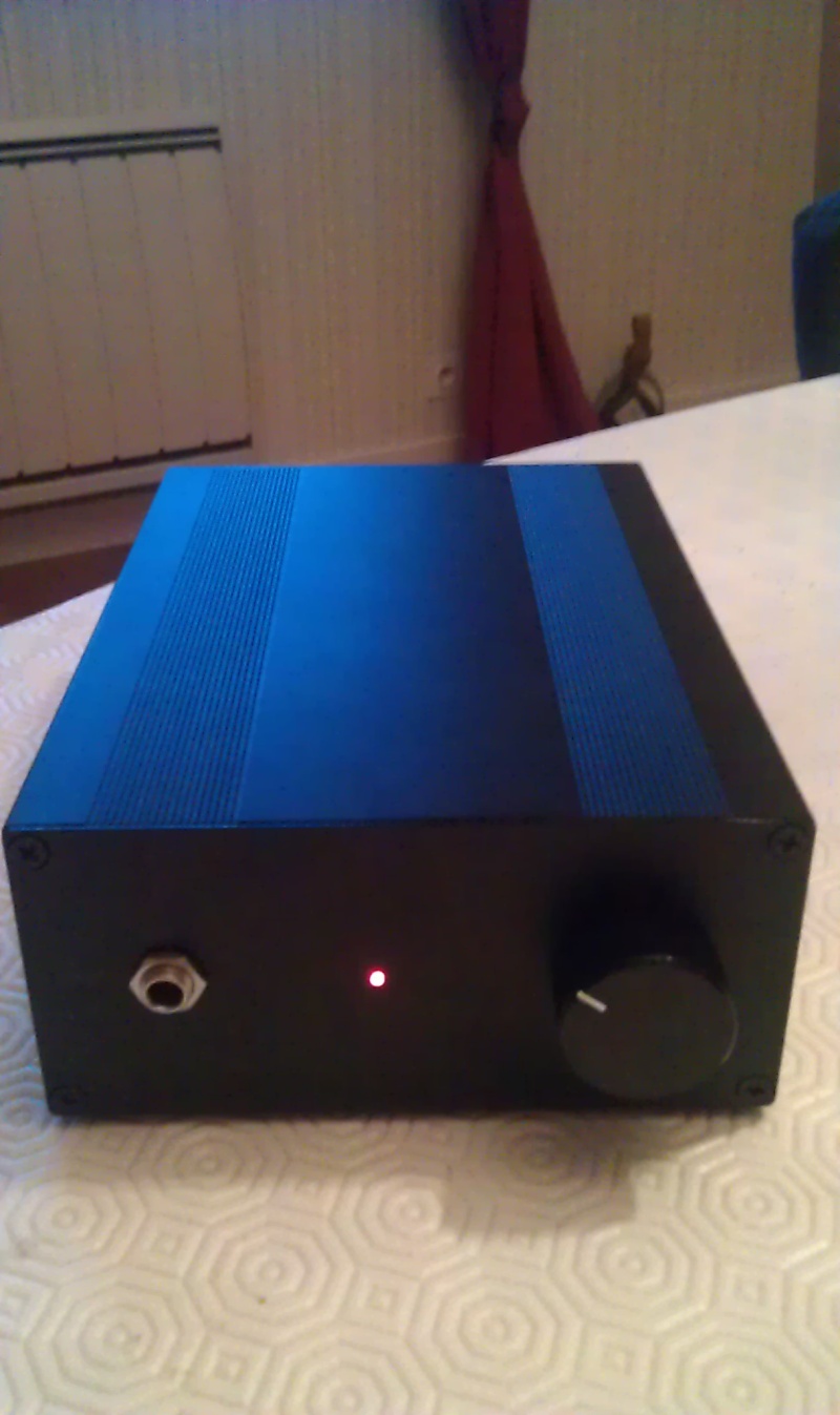
Hi guys this is my first DIY audio project, it's a Headphones Amplifier based on a OPA2107 opamp, BD139/140 transistors and ELNA SILMIC II electrolytic capacitors.
Features:
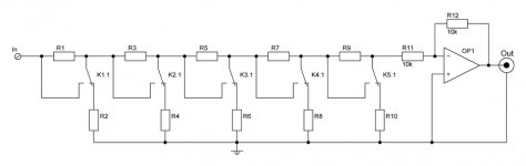
· +20dB stereo volume control
· 10 kΩ input impedance
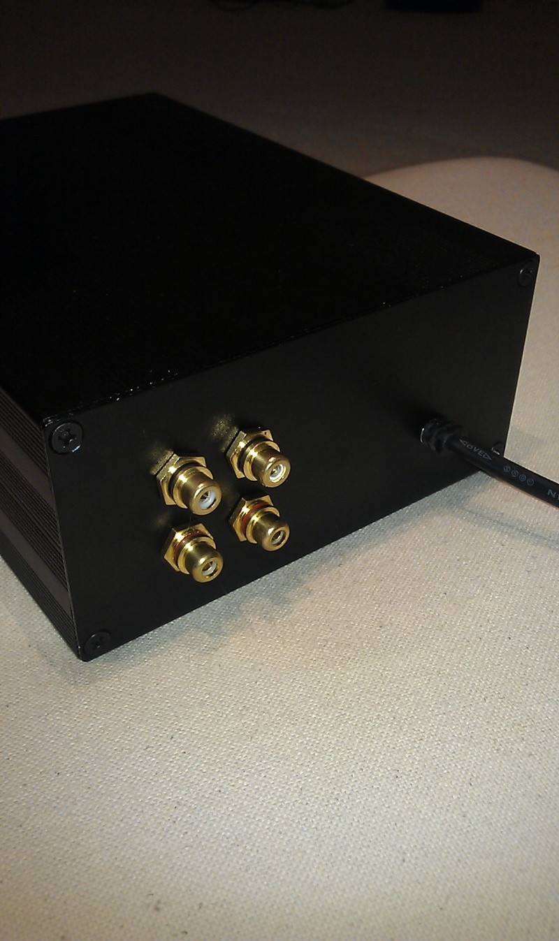
· RCA line input
· RCA amplified output
· AC 230V
· On LED
Source is Philips CD824 CD player.
It will drive AKG K702 open-back headphones (i will get them in few days...)
PDF circuit and photos are attached
I will really appreciate your comments.

Features:
· +20dB stereo volume control
· 10 kΩ input impedance
· RCA line input
· RCA amplified output
· AC 230V
· On LED
Source is Philips CD824 CD player.
It will drive AKG K702 open-back headphones (i will get them in few days...)
PDF circuit and photos are attached
I will really appreciate your comments.
Attachments
· 10 kΩ input impedance
That looks like ESP project 113. But you are using a FET input op-amp, allowing some refinements compared with project 113.
The input impedance will vary between 10 k and 6.8 k, depending on the position of the potentiometer.
For this reason, R17/R11 should be 100 k or bigger.
C10/C14 can then be a good quality film cap of around 0.22 to 1 uF.
I would remove C11/C15. DC offset should be negligible.
You should add two 100 - 470 uF decoupling caps on the output stage and 0.1 to 1 uF at the op-amp supply pins.
Optional but recommended:
- An RF filter in the input network
- Zobel network on the output.
It is surprisingly easy to push these circuits into oscillation. You should test with different combinations of headphones/headphone cables.
That looks really nice.
If you don't mind me asking...
Why such a high gain? I admittedly don't know much about the headphones your are trying to drive, but I doubt they require that much gain.
The buffer looks like a Sijosae discrete rail splitter. I like it. In fact, I have used very similar designs in Guitar amps. That would make a mint tone stack/reverb driver.
I don't understand the need for the R9/R16 1k resistors. If it is something important that I'm missing, it wouldn't be the first time. After about five minutes of mild thought, I don't see the need for them at all. If it's for attenuation, then you need to change R19 and R20 instead.
If you are speaking about R_IN and L_IN, the impedance is fixed at 10k (measured)The input impedance will vary between 10 k and 6.8 k, depending on the position of the potentiometer.
C10/C14 are 10µF ELNA SILMIC II electrolytic.
What is a Zobel network?
I measured a 1 MHz oscillation (less than 1mV and independent of the source/load) coming from op ampIt is surprisingly easy to push these circuits into oscillation. You should test with different combinations of headphones/headphone cables.
I can't explain the origin (i changed for TL072 and NE5532 : no effect).
Another thing I can't explain : when I set R19/R20 higher (47k), a kind of white noise appears...
If you are speaking about R_IN and L_IN, the impedance is fixed at 10k (measured)
Impedance is measured at AC, not DC.
For AC analysis C10/C14 is considered a short circuit, so input impedance is R11/17 in parallel with part of the potentiometer.
At minimum volume setting the impedance is simply 10k.
At maximum volume setting it is ~6.8k.
The 22k is 'loading' the potentiometer, changing its (logarithmic) curve somewhat.
This is not that important, but to minimize the effect just make R11/17 more than 10x the size of the potentiometer.
C10/C14 are 10µF ELNA SILMIC II electrolytic.
A good electrolytic is still worse than a bad film capacitor in this position.
An added benefit of increasing R11/17 in size is that it allows you to use a smaller value capacitor here, making film capacitors a practical option.
What is a Zobel network?
Zobel network - Wikipedia, the free encyclopedia
You will see one on the output of most audio amplifiers.
Just add a 10 to 47 ohm resistor in series with a 100 nF from the output of the amp to ground.
It helps to stabilize the amplifier with inductive loads.
Optionally also add a 10 ohm paralleled with a ~10 turn 15 mm diameter coil in series with the output. It isolates the amp from capacitive loads (e.g long headphone cords).
I measured a 1 MHz oscillation (less than 1mV and independent of the source/load) coming from op amp
I can't explain the origin (i changed for TL072 and NE5532 : no effect).
Another thing I can't explain : when I set R19/R20 higher (47k), a kind of white noise appears...
That is a gain of 48, very high for a headphone amp.
A gain of 4 to 11 is more typical, depending on the source and the headphones.
Make sure the input is shorted when you do this test. A DAC can give some inaudible high-frequency garbage for example, even when idling.
You do not seem to have oscillation problems (1 mV?), but you can improve the phase margin by adding 47 to 100 pF local feedback on the op-amp (OUT to IN-).
Make sure to add the additional bypass capacitors on the op-amp and buffer supplies.
^ Seconded. (Except I'd say 22..100 pF.)
A 1µ film input coupling cap should be fine even with the 22k. Do note that low-frequency noise can be expected to increase with a smaller cap due to impedance seen by amp being 22k || (Z_C + R_source). Nothing that would bother us audibly I guess, but it would be measurable. As a compromise, you can use a bipolar electrolytic.
C11/15 should also be bipolar.
When using OP types with lower voltage noise like 5532, the values of R9/16 and R12/18/19/20 may be reduced to about 1/2 to 1/3. This would mainly be of interest at higher gains or with higher-sensitivity 'phones though.
C12/13 and C18/19 can be replaced by one single cap going across the diodes. Doesn't look like it achieves exactly the same at first glance, but at least in simulation it does.
I would recommend putting a small trimpot in series with the bias diodes for some idle current adjustment. (100 ohms or so.) Currently idle current would rather be less than 2 mA (measured yet?). Aim for 5..10 mA. Ideally, mount both output transistors and their bias diodes on a common heatsink.
A measly 1 ohm of output series resistance can keep you out of a lot of trouble. Very few cans insist on lower values (some multi-driver BA IEMs are up to 1 dB of FR deviation at 1 ohm, but in most cases anything under 10 ohms is fine).
A 20 dB gain seems adequate for K701s, which are on the voltage hungry side for their nominal 62 ohms (about 100 dB SPL per 1 Vrms).
Why that old "LM317 for negative voltages" trick? LM337s have been existing for pretty much as long.
Last edited:
What do you mean by low frequency noise?A 1µ film input coupling cap should be fine even with the 22k. Do note that low-frequency noise can be expected to increase with a smaller cap due to impedance seen by amp being 22k || (Z_C + R_source). Nothing that would bother us audibly I guess, but it would be measurable. As a compromise, you can use a bipolar electrolytic.
OK thanks for the adviceWhen using OP types with lower voltage noise like 5532, the values of R9/16 and R12/18/19/20 may be reduced to about 1/2 to 1/3. This would mainly be of interest at higher gains or with higher-sensitivity 'phones though.
There is currently a THD of less than 0.006% at full pot and HP loaded so crossover distortion is absent : no need to change the setup.I would recommend putting a small trimpot in series with the bias diodes for some idle current adjustment.(100 ohms or so.) Currently idle current would rather be less than 2 mA (measured yet?). Aim for 5..10 mA. Ideally, mount both output transistors and their bias diodes on a common heatsink.
The heatsink is not very useful because of low dissipation, I wanted the circuit and PCB to be simple as possible.
What kind of trouble?A measly 1 ohm of output series resistance can keep you out of a lot of trouble.
ExactlyA 20 dB gain seems adequate for K701s, which are on the voltage hungry side for their nominal 62 ohms (about 100 dB SPL per 1 Vrms).
")
It's not a trick : with a double secondary transformer you have two +15V supplies independent... it's making the PCB routing the same on both rails.Why that old "LM317 for negative voltages" trick? LM337s have been existing for pretty much as long.
Noise at low frequencies up to a few hundred Hz. The impedance seen by the amplifier input rises as input coupling cap impedance does, with the corresponding effect on thermal (Johnson) noise density.What do you mean by low frequency noise?
Stability when driving capacitive loads. In critical cases, that one ohm can help a lot. Have you tested capacitive load driving capability? You'll need at least 2 nF, though I'd shoot for at least 10 nF or even unlimited (>= 1 µF).What kind of trouble?
So it's the expected laziness.It's not a trick : with a double secondary transformer you have two +15V supplies independent... it's making the PCB routing the same on both rails.
As long as it works fine...Headphones are inductive loads so why testing capacitive loads?Stability when driving capacitive loads. In critical cases, that one ohm can help a lot. Have you tested capacitive load driving capability? You'll need at least 2 nF, though I'd shoot for at least 10 nF or even unlimited (>= 1 µF).
About resistors values in a op amp circuit, in general lowering values will lowering noise so what is the disadvantage of it?
cables are largely capacitive at the feedback unity gain intercept frequency of many op amps, discrete audio amps - I use use ~ 100 pF to ~ 1 nF output load in sim, real world to check stability
a local feedback C right at each op amp from output to -in is one way to improve stability - few x 10 pF - does slow down the op amp, reducing feedback around the output Q
with high feedback network R values often a few pF local feedback C is required to avoid peaking caused by the high feedback R and the op amp's own input pin's parasitic C
usually the DC blocking C in the feedback leg is connected to gnd for this same reason - the blocking C are usually lots bigger physically than the R and add more parasitic C to the op amp -in circuit node
and a RF bypass C to gnd right at the +in pins of the op amps can improve loop phase shift too
- you probably want this to give RC filter corner frequency with the worst case volume pot setting R of > 200 kHz
if you need low Audio output Z you can use inductive output decoupling, can be done with inductors, inductors paralleled with R, or lossy ferrite "bead cores" slipped over the output wire
many Audio amp outputs use both the series decoupling Z and the Zobel RC to gnd to define a resistive Z to gnd for the amp output near the loop gain intercept frequency
and of course with wall power there is some quality improvement available from Class A output stage bias - adding one more diode to each bias string for ~ 70 mA more bias would give full Class A operation for many headphones - you may need heatsinking for the extra ~ 1 W of continuous power in each Q
Last edited:
Output loading and power dissipation mostly.About resistors values in a op amp circuit, in general lowering values will lowering noise so what is the disadvantage of it?
These guys are all giving you really-excellent and complete advice, and you should implement ALL of it.
However, before doing anything else, you must be sure to connect a 0.1 uF X7R ceramic capacitor from RIGHT AT each opamp power pin to ground, and parallel each of those with a 10 uF electrolytic that can be a few millimeters farther away from each power pin.
And you must put at least 100uF electrolytic in parallel with (each of) C7, C8, C16, and C17.
NOTE, too, that R19 and R20, as well as R16 and R9, should be connected VERY close to the opamp pins.
I used a 10k ALPS Audio Potentiometer for volume control and it works perfectly, very smooth and no scratch sounds.hey aftermath does your volume control buffer works ok,no highs cut?
would you recommend this instead ?
The frequency response of my preamp is absolutely flat from 20Hz to 20kHz and above.
- Status
- This old topic is closed. If you want to reopen this topic, contact a moderator using the "Report Post" button.
- Home
- Amplifiers
- Headphone Systems
- "The Burst" DIY Headphone Amplifier