Any 9V-type battery will work without mods.
Battery charge time depends on state of discharge and capacity, so voltage isn't a concern.
Even with the 9.6v not the 8.4v?
Thanks sofaspud. Thats what I thought but I wanted to double check. I have little experience with NI-MH charging circuits and the last thing I want is to mess up the amp I just built.
I have enough parts to make a second amp and I think I am going to try the upgrade on the coupling caps that AGDR talks about in post 7. The sims look like it improves low end response and phase (if I am reading the graph right). This may not make an audible difference on all headphones but if I try using the amp for a few other purposes it might make a difference.
I have enough parts to make a second amp and I think I am going to try the upgrade on the coupling caps that AGDR talks about in post 7. The sims look like it improves low end response and phase (if I am reading the graph right). This may not make an audible difference on all headphones but if I try using the amp for a few other purposes it might make a difference.
O2 current buffer mod for AKG K550s
This is a reply to a post by ethanolson in the main O2 thread here: http://www.diyaudio.com/forums/head...headphone-amp-diy-project-51.html#post3058511. Since it involves modifications I figured best to post it here.
I ordered a pair of K550s a few days ago. Although I haven't received and tried them yet, just from the specs (SPL = 114dB/V) it looks like no voltage gain will be needed like you are showing - attenuation needed in fact with my sources - just potentially need some current buffering. So I'm in the process of stripping down an O2 for fun to be just a current buffer, specifically to work with the AKG K550s.
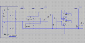
The first gain stage (U1, the NJM2068) is removed along with the 10K input resistors R14 and R20. The input signals on each channel are then run directly to the pot sections (which are also 10K, so the input RF filter still gets formed with C11 & C12 with the same corner frequency), which then allows signal attenuation. All of the gain and compensation parts are removed or disconnected as not needed here: R16,17,19,20,21,23; C19,20; S2. Then for the output stage current buffers I'm removing one of the 1R output resistors, R11 & R18, on each channel (so the two op amp sections are not in parallel anymore - only need 1/2 of each NJM4556 for the K550's low current requirements). Then jumpering the remaining 1R on each channel, R10 & R15, so there is O ohm output resistance (the 1Rs are not needed to balance anymore if the op amp sections are not in parallel). Then I'm going to drop the voltage rails to +/- 6Vdc (or maybe +/-5Vdc) with LM7806/LM7906 regulators and a 9VAC power transformer (or maybe can just use LM78L06/LM79L06, the 100mA TO92 versions) since the K550 should only need around 1.1Vpeak, absolute max.
For batteries I'm going to try using a couple of 3.6Vdc 600mAh NiMH wireless phone batteries. At least that is the plan right now, along with adjusting the power management circuit to work with the new lower rail voltages.
The net result is sort of a mini version of OPC's "Wire" headamp that is just a current buffer.") Once I get it built and tested with the phones I'll post details in the mod thread. If someone gets something similar built first and tested, please post the results!
Once I get it built and tested with the phones I'll post details in the mod thread. If someone gets something similar built first and tested, please post the results!
Congratulations again to RocketScientist for coming up with such a versatile design.
This is a reply to a post by ethanolson in the main O2 thread here: http://www.diyaudio.com/forums/head...headphone-amp-diy-project-51.html#post3058511. Since it involves modifications I figured best to post it here.
I ordered a pair of K550s a few days ago. Although I haven't received and tried them yet, just from the specs (SPL = 114dB/V) it looks like no voltage gain will be needed like you are showing - attenuation needed in fact with my sources - just potentially need some current buffering. So I'm in the process of stripping down an O2 for fun to be just a current buffer, specifically to work with the AKG K550s.
The first gain stage (U1, the NJM2068) is removed along with the 10K input resistors R14 and R20. The input signals on each channel are then run directly to the pot sections (which are also 10K, so the input RF filter still gets formed with C11 & C12 with the same corner frequency), which then allows signal attenuation. All of the gain and compensation parts are removed or disconnected as not needed here: R16,17,19,20,21,23; C19,20; S2. Then for the output stage current buffers I'm removing one of the 1R output resistors, R11 & R18, on each channel (so the two op amp sections are not in parallel anymore - only need 1/2 of each NJM4556 for the K550's low current requirements). Then jumpering the remaining 1R on each channel, R10 & R15, so there is O ohm output resistance (the 1Rs are not needed to balance anymore if the op amp sections are not in parallel). Then I'm going to drop the voltage rails to +/- 6Vdc (or maybe +/-5Vdc) with LM7806/LM7906 regulators and a 9VAC power transformer (or maybe can just use LM78L06/LM79L06, the 100mA TO92 versions) since the K550 should only need around 1.1Vpeak, absolute max.
For batteries I'm going to try using a couple of 3.6Vdc 600mAh NiMH wireless phone batteries. At least that is the plan right now, along with adjusting the power management circuit to work with the new lower rail voltages.
The net result is sort of a mini version of OPC's "Wire" headamp that is just a current buffer.
Once I get it built and tested with the phones I'll post details in the mod thread. If someone gets something similar built first and tested, please post the results! Congratulations again to RocketScientist for coming up with such a versatile design.
Last edited:
This sounds really good to me for my IEMs and my hope of eventually getting the K550.
I thought about doing the same kind of thing, but your approach is more involved and more logical than my thoughts. For instance, I didn't consider removing the output resistors, but I did consider reducing their rating.
I thought about doing the same kind of thing, but your approach is more involved and more logical than my thoughts. For instance, I didn't consider removing the output resistors, but I did consider reducing their rating.
I thought about doing the same kind of thing, but your approach is more involved and more logical than my thoughts. For instance, I didn't consider removing the output resistors, but I did consider reducing their rating.
I was glad to see your post in the O2 thread!
I had worked out some numbers in my head that seemed to show that just various levels of attentuation would be needed with the AKG K550s, no voltage gain, and that is what you came up with too. I ran some LT Spice simulations, below. The first concern with the modification is whether the single section of the NJM4556 can handle the current load of the 32R K550s at normal listening levels, or if the parallel buffers would be needed. A second concern is stability against oscillation in removing the 1R output resistors entirely with a typical headphone cable capacitive load. A third concern is whether the new +/-6Vdc power supply rails provide enough voltage headroom across the output devices in the NJM4556 when pushing 36mA(peak) or so.
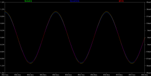
My back of the envelope math seemed to indicate that a single section would do, since 1.1Vpeak going to the phones (which should be super loud as ethanolson mentioned given the K550s sensitivity) should be around 36mA(peak) [= 25mA(rms)]. Sure enough, that is what the first plot below shows. Green is the 1.1Vpeak input signal to the amp (and on to the phones since the "pot" is all the way up), blue the output from the 1:1 current buffer, and red the load current on the right axis. I still have 390pf across the 32R load to simulate some headphone cable capacitance.
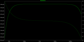
The second plot is the frequency response. Still the same as the unmodified O2, as it should be, with the exception of a slightly higher RF 3dB point since RocketScientist had some compensation in the gain stage.
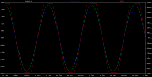
The third plot is an intentionally huge input signal to force clipping, to roughly test the accuracy of the device math model being used for the NJM4556. The output current for the single section limits at 70mA, exactly like it is supposed to, and the voltage overhead (output device minimum resistance in the chip) of the NJM4556 is about 4Vdc at 70mA (2Vdc across the phones = 6Vdc rails total). That is better than I was expecting. My back of the envelope came up with about 4V at the 36mA, which is why I picked +/-6Vdc rails. This would indicate +/-5Vdc rails may work for normal listening levels, but that is starting to split hairs and would have to be confirmed with some scope measurements. I'm leaving the rails at +/-6Vdc to allow some extra voltage headroom.
With the gain stage gone one slightly negative effect will the input impedance and upper (RF) corner frequency varying slightly with the pot position, since the 40.2k bias resistors on the output stage are in parallel (ac circuit model) with the pot wiper. Shouldn't make a bit a difference with any sort of normal source device, from what I can tell. On the plus side no forced clipping with large input signals, like my two sources that output 2Vdc, since the pot attentuates the input signal from 0.0->1.0 the standard way.
Input power to the NJM4556 chip would be around 25mA(rms) * 6V = 150mW. Subtract what the phones use per channel, (25mA)^2 * 32 = 20mW leaves about 130mW dissipated in the chip. Well within specs of 350mW per half (700mW total for the DIP8 chip). I've shown in previous posts you really have to plot a few points vs. output voltage level to find max chip dissipation, but this is far enough within specs it should be just fine.
Attachments
-
 O2 current buffer circuit 2.5kHz 1.1Vpeak input 32R 390pF load.png37.4 KB · Views: 373
 -
 O2 current buffer plot 2.5kHz 1.1Vpeak input 32R 390pF load.png26.5 KB · Views: 370
 -
 O2 current buffer AC plot 5Hz to 500kHz 32R 390pF load.png20.9 KB · Views: 363
 -
 O2 current buffer plot 2.5kHz 2.8Vpeak input 32R 390pF load.png29.6 KB · Views: 359
Last edited:
O2 K550 current buffer mod is close to the Grado RA1
Well it just occurred to me that the net result of the O2 current buffer modification for the AKG K550s, above, is rather close to what is inside the Grado RA1 headphone amplifier that goes for $350.
Here: http://web.archive.org/web/20091027...es.com/rubin_jpk/rubin_images/GRADO_schem.gif (wayback machine, give it 15 seconds)
The RA1 uses a single section of the NJM4556 with no output resistor, just as in this O2 mod. The RA1 has the NJM4556 wired for voltage gain though, where in the O2 it is just a unity gain current buffer. The RA1 runs on +/-9V while this mod runs on +/-6V. The RA1 uses a 100k pot and 5uF coupling cap, whereas RocketScientist's circuit uses a 10K pot and 2.2uF cap, which are just fine.
Last edited:
I once saw a RA-1 schematic using an inverting configuration... then the high-value feedback resistors make sense at least.
Essentially you're turning the O2 into the "cMoy with no gain" that RocketScientist reviewed at one point (well, a slightly better designed version anyway). If minimal current consumption is paramount and the source can easily drive a 10k pot, the mods as stated make sense - but do note that with only one set of buffers, distortion when driving low-impedance loads (K550s included) will be a factor of 2 worse.
It would be interesting to know how a single 4556 fares against the proposed low-power solution, 2x OPA2277.
How do you intend to "unparallel" the 4556 halves without PCB surgery? The two noninverting inputs are tied together after all...
Last edited:
O2 current buffer mod for AKG K550s - input only 80mV
Good thoughts! To unparallel I'm just unsoldering R11 and R18 - the op amp inputs remain connected. So the second half of the op amp on each channel will get a signal, the output just won't go anywhere. Then I'm shorting R10 and R15 on the remaining (connected) sections for zero ohm output impedance.
I was wondering about those large feedback resistors in the RA1 schematic! You are quite right, the result is a CMOY with a gain of 1, the power management circuit, and a really good PCB layout (which is half the battle right there).
I received the K550s today and I have to say I'm impressed! These things totally rock IMHO.
But... I can also see that my input voltage assumptions in the writeup above for the current buffer are too high by an entire order of magnitude. I've measured reasonable listing levels with the K550s at around 60mV to 80mV. That matches up with the "hearing damage warning" on the box, for the wide band characteristic voltage (here: AP High Performance Audio Analyzer & Audio Test Instruments : Service & Support) to produce 94dB, at only 135mV.
Good grief. These things (K550s) don't need an amplifier, either voltage or in many cases current buffer. 80mV(rms) into the 32R is only 2.5mA, easily handled by many standard op amps. No super high current buffer op amps needed here. In fact, with the mod outlined above, LME49720s (or possibly the NJM2068 if unity gain stable) could be used in place of the NJM4556s for lower noise and distortion. RocketScientist points out that the NJM4556s were a bit of a trade off for high current capability that many phones need. The 49720 is good for 26mA or so per channel.
About the only remaining reasons to even use a current buffer with the AKG K550s would be (1) lower output impedance for better damping, if the source Z(out) is not << 32R or (2) if the source really is expecting 10K input, probably like many DACs, where even 2.5mA would be an order of magnitude too much current to supply. But I would think that most any source with a "headphone" output will be able to power the K550s with no amplifier of any kind needed.
How do you intend to "unparallel" the 4556 halves without PCB surgery? The two noninverting inputs are tied together after all...
Good thoughts!
To unparallel I'm just unsoldering R11 and R18 - the op amp inputs remain connected. So the second half of the op amp on each channel will get a signal, the output just won't go anywhere. Then I'm shorting R10 and R15 on the remaining (connected) sections for zero ohm output impedance.I was wondering about those large feedback resistors in the RA1 schematic! You are quite right, the result is a CMOY with a gain of 1, the power management circuit, and a really good PCB layout (which is half the battle right there).
I received the K550s today and I have to say I'm impressed! These things totally rock IMHO.
But... I can also see that my input voltage assumptions in the writeup above for the current buffer are too high by an entire order of magnitude. I've measured reasonable listing levels with the K550s at around 60mV to 80mV. That matches up with the "hearing damage warning" on the box, for the wide band characteristic voltage (here: AP High Performance Audio Analyzer & Audio Test Instruments : Service & Support) to produce 94dB, at only 135mV.
Good grief. These things (K550s) don't need an amplifier, either voltage or in many cases current buffer. 80mV(rms) into the 32R is only 2.5mA, easily handled by many standard op amps. No super high current buffer op amps needed here. In fact, with the mod outlined above, LME49720s (or possibly the NJM2068 if unity gain stable) could be used in place of the NJM4556s for lower noise and distortion. RocketScientist points out that the NJM4556s were a bit of a trade off for high current capability that many phones need. The 49720 is good for 26mA or so per channel.
About the only remaining reasons to even use a current buffer with the AKG K550s would be (1) lower output impedance for better damping, if the source Z(out) is not << 32R or (2) if the source really is expecting 10K input, probably like many DACs, where even 2.5mA would be an order of magnitude too much current to supply. But I would think that most any source with a "headphone" output will be able to power the K550s with no amplifier of any kind needed.
Last edited:
The O2 has a way of quieting poorer audio equipment's noise and it has a lower output impedance, as you noted, which add up to a better listening experience overall.
If I understand correctly, the O2 has such good performance in part because it divides the audio across two NJM4556 opamps and therefore has lower distortion (for the operating demands of this circuit, at least). I'm also under the impression that lowering the voltage raises the noise floor in the opamps. I don't remember what voltage is optimal for the NJM4556, but I seem to think that it's 12-15V.
One last thought: input impedance imbalance. Is the pot absolutely consistent in terms of input impedance? If it gets imbalanced (possible poor channel matching), won't that have some negative effect on the source?
Moving right along... the next mod I'm thinking up is variable gain but still with the hi/lo switch and the low position being a voltage divider circuit. Thoughts?
If I understand correctly, the O2 has such good performance in part because it divides the audio across two NJM4556 opamps and therefore has lower distortion (for the operating demands of this circuit, at least). I'm also under the impression that lowering the voltage raises the noise floor in the opamps. I don't remember what voltage is optimal for the NJM4556, but I seem to think that it's 12-15V.
You are quite right about the voltage vs. noise! Here is a good recent article: AV: Low-Voltage Audio Products: Power & Noise - Pro Sound Web . I'm assuming though that the noise floor will still be way below audible levels, even if it is up a bit. That is something that would have to be verified with the good equipment though, RocketScientist's dScope or an AP. With any of these measured parameters I'm always of the mindset that if it is below my threshold of hearing, it doesn't exist even if I can measure it.
The voltages and currents involved here with the AKG K550s are so low that it might be worth looking into some +/-5V op amps, if any exist with good audio specs.RocketScientist definitely did some smart things with the O2 - stuff that never would have occurred to me. Separating it into two stages was one. Going from unity (1) gain to anything higher on op amps seems to degrade performance. RS did some of his dScope measurements on the NJM4556 at gain=1 on his website, if I'm remembering right, then again at gain=2 and the numbers decreased. By moving the voltage gain off to a separate stage he was able to use a (lower output current) lower noise, lower distortion chip for the gain (and the chip didn't have to be unity gain stable). Then the current buffer could run at gain=1. So the paralleling of the NJM4556s isn't what helped reduce noise and distortion, I don't believe, that just increased output current. Moving the voltage gain to a separate stage with a better chip was the key. But here we don't need any voltage gain at all with the K550s so one stage with unity gain will do the job.
One good exception to the two-stage design is compromising a little bit to reduce parts count, like AMB did with the Mini-3. Distortion and crosstalk levels may be higher, although I'm still not sure they are above audible threshold levels, but the result is a super-small amp by making the one single op amp do voltage gain and current output. Two stages produced better measured numbers but require more chips and twice the space.
Having that 40.2K resistor across the 10K pot wiper will probably (a guess, haven't done the math) at worst make a 1K or so difference in input impedance with the current buffer mod. So as the pot is turned the input impedance may vary between 9K - 10K. I should plot that out from 0K to 10K on the pot wiper for fun and see what it really is. For sources with fairly low output impedances that shouldn't matter. I haven't done squawk with tube based amp design, so really can't speak there, but I keep seeing mention of tube sources being more sensitive to loading. Maybe it would matter with a tube based source.
Good thoughts about the pot imbalance issue. The natural tracking imbalance that occurs between the two pot sections (left and right channel) will affect any audio device, including the original O2. Even the good analog pots like the Alps or Bourns Pro Audio only track within 20% or so between the sections as I recall. A person would have to go to a step attenuator with 1.0% or 0.1% resistors to do better. So that tracking issue between pot sections shouldn't affect this current buffer any more or less than the regular O2 or any other amp, at least from what I can see now.
Well I spent three hours listening to the AKG K550s last night with all kinds of music. Hard to put them down.
These things are fantastic. They don't make my left earlobe sore from rubbing (the K550s don't rub at all) after just 30 minutes as happens with my Shure SRH940s. Headphones shouldn't take off skin!! I also find that I don't need bass boost anymore with the K550s, either the circuit mod or to eq in bass boost in the player, like I've had to do with the Shure 940s.
Last edited:
O2 AKG K550 current buffer mod - DC offset reduction
Here is another interesting issue related to running the new AKG K550 headphones with a unity gain current buffer, like a modded O2 amplifier. With the high sensitivity of these phones - just 60mV to 80mV for standard listing levels - DC offset in an amplifier output becomes a bigger percentage of the swing voltage.
For the typical 3mV DC output offset in the O2 amp with a less sensitive headphone that uses, say, a 1Vrms swing for normal listening levels, that offset is just 3mV / 1000mV = 0.3% of the swing. But with the K550s a 3mV DC offset now becomes 3mV / 60mV = 5% of the output voltage swing and results in a greater chance that the applied DC moving the voice coil off-center will matter. 3mV of DC is still probably within design specs for the headphones - I have an email into AKG to find out - but lower offset can probably be had in a couple of ways.
One way to get lower DC output offset is with chips that have lower input bias current and/or offset voltage specs. Earlier in the mod thread here I did some measurements with the LME49860 replacing the NJM4556 as the output chip(s), the high voltage version of the LM49720, both of which have less than 1/10 the input bias current (10nA vs. 180nA) and 1/5 the input offset voltage. In the actual tests I posted the DC offset voltage was 0.3mV, 1/10 as expected, on one channel and 0.0mV on the other - below the LSB of the meter.
If the LME chips are used the 1R output resistors should probably remain for stability and the sections paralleled, as in the unmodified O2, since the rated capacitance direct-drive capability of each chip section is just 100pF, less than the typical headphone cable. The LME chips also have built in short circuit protection like the NJM4556 so they should also survive use with the TRS output jack.
The other way that should work was posted by Regal earlier in the thread. The PC trace that directly connects the output on each NJM4556 chip section to the inverting input, to form the unity gain buffer, can be cut and a 40.2K resistor soldered in. SMD resistors would probably work well. With this mod the input bias current into the inverting input should cause roughly the same voltage drop across the new 40.2K resistor as the non-inverting does with the original 40.2K resistor. The two voltage drops should then roughly cancel out in the differential input.
Last edited:
with sensitive phones my experience is DC offset can be a significant impact to SQ. It makes sense when you think about how a driver works, and your numbers show it is a significant deflection, has to affect fr resonance, waterfall plot, etc.
I have to admit that my O2 has turned from serving headamp amp duty to tool duty. I just don't like the O2's treble as much as my tube SET. And where my SET fails (power for orthos), the O2 does fails also.
The O2 design is really much like an instrumentation amp. With a multimeter I use it to easily make great soundcard measurements of audio gear with up to the ~9v rms input clipping) this allows measuring say a small power amp volume cranked up to 20w into 4 ohms. So it serves as a almost negligible distortion and noise buffer with the Asus soundcard+art as the signal generator. Poor man's dscope.
I put in an email to RocketScientist/NwAvGuy about the DC offset issue and use of my Shure E2c IEMs and his response is as follows:
-------------
Yes, you can experiment with cutting the 4556 feedback traces and using a resistor of around the same value as is on the other input pin. Unfortunately you need a resistor for each op amp section (4 total) which there just wasn't room for on the PCB while still maintaining an otherwise decent layout. If you only need one op amp section per channel that simplifies things a bit.
If you don't want that big of "hack" you can also just drop the value of the input resistor to around 10K which will proportionately lower the offset and raise the -3 dB cut off frequency which is current so low it can move up with no harm.
But, to be honest, I really don't think 3 of 4 mV of offset is anything to worry about even with Sure IEMs. The FiiO E10, for example, has 13 mV in low gain mode and over 30 mV in high gain mode.
The "driver offset" will be negligible at < 4 mV. I don't think it will significantly change the driver performance. I have a "fake ear" (damped vinyl tube for my calibrated lab microphone) that I use for some headphone tests. I played around briefly with offsets up to tens of millivolts and didn't notice any difference in frequency response or distortion performance from my IEMs. I didn't test everything but I really doubt 4 mV will make any audible difference.
The reason is the linear range of the IEM driver is much greater than the offset. So you're just ever so slightly shifting the operating point of the driver and the only effect will be an ever so slight change in the overload behavior as you approach the limits of the driver (very slight asymmetrical "clipping" for lack of a better description). But, we're talking such a small amount the mechanical tolerances of the drivers probably create bigger asymmetrical differences. And we're also talking about hearing damaging volume levels.
-------------
So... I'm still not content to have an imperfection, so I'd like to get something better worked out. I suspect a trim resister on each output opamp and tuned in manually would be the most ideal. It might be easier to dial in with series resistance and a lesser value trimmer.
-------------
Yes, you can experiment with cutting the 4556 feedback traces and using a resistor of around the same value as is on the other input pin. Unfortunately you need a resistor for each op amp section (4 total) which there just wasn't room for on the PCB while still maintaining an otherwise decent layout. If you only need one op amp section per channel that simplifies things a bit.
If you don't want that big of "hack" you can also just drop the value of the input resistor to around 10K which will proportionately lower the offset and raise the -3 dB cut off frequency which is current so low it can move up with no harm.
But, to be honest, I really don't think 3 of 4 mV of offset is anything to worry about even with Sure IEMs. The FiiO E10, for example, has 13 mV in low gain mode and over 30 mV in high gain mode.
The "driver offset" will be negligible at < 4 mV. I don't think it will significantly change the driver performance. I have a "fake ear" (damped vinyl tube for my calibrated lab microphone) that I use for some headphone tests. I played around briefly with offsets up to tens of millivolts and didn't notice any difference in frequency response or distortion performance from my IEMs. I didn't test everything but I really doubt 4 mV will make any audible difference.
The reason is the linear range of the IEM driver is much greater than the offset. So you're just ever so slightly shifting the operating point of the driver and the only effect will be an ever so slight change in the overload behavior as you approach the limits of the driver (very slight asymmetrical "clipping" for lack of a better description). But, we're talking such a small amount the mechanical tolerances of the drivers probably create bigger asymmetrical differences. And we're also talking about hearing damaging volume levels.
-------------
So... I'm still not content to have an imperfection, so I'd like to get something better worked out. I suspect a trim resister on each output opamp and tuned in manually would be the most ideal. It might be easier to dial in with series resistance and a lesser value trimmer.
O2 current buffer offset reduction mod tests
Well, I did it. Mod built and tested below, complete with pictures, using both regal's feedback resistor and a LME49720 in the same circuit. Either way worked well, below.
regal: Interesting thoughts about the offset! I agree the O2 would probably make a good instrumentation amp, given the low noise floor and distortion. With the coupling caps removed it could even be used with DC things like strain gauges. I'll bet it would be very linear from that -9Vdc t0 +9Vdc.
ethanolson: thank you for getting RocketScientist's input!
This is using an O2 that is built up the standard way with the two output op amp sections still in parallel on each channel. For just testing offset reduction here I didn't want to also mix in unparalleling them yet.
I replaced one NJM4556 with a LME49720. For the other one I built up regal's feedback mod, putting a 40.2k resistor between pins 1 and 2, and another between pins 6 and 7 after disabling the existing PCB short between those pins for unity gain. In actual practice that turned out to be a bit harder than it seemed, since the PCB traces that connect 3 of those 4 feedback loops (both 4556 op amps) are on the top of the PC board, covered up by the IC sockets if you all ready have the board built, which would require removing sockets to cut the traces.
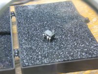
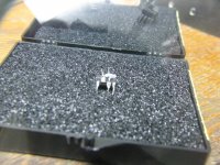
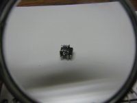
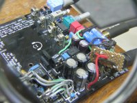
Instead I bent pins 2 and 6 on a NJM4556 up and soldered the two 40.2k feedback resistors on top of the chip. Bending the pins up disconnects them from the PCB traces (they don't go into the socket holes), of course. The first picture below is the NJM4556 with the two pins bent up. The second picture is the resistor from pins 6-7 crimped on before soldering, and the third picture is both resistors soldered on. In the final picture that is an LME49720 in the rightmost NJM4556 position, and of course the modified NJM4556 in the left position.
The LME49720's DC offset actually measured 0mV, below the LSB of the meter. The the NJM4556 measured 1.5mV, down from the 3mV I measured before modding it, so the feedback resistor modification worked well.
The interesting thing was the listening test. I could hear (completely subjective, your mileage may vary!) that one channel seemed to have a bit better sounding bass than the other. I assumed the good bass was probably the NJM4556, since it had the best current capability. So to save from tracing wires to find out which channel was which chip, I just pulled out the LME49720 chip and powered it up expecting the better bass channel to be remaining. To my surprise that was the wrong channel. The LME49720 was the one with the better sounding bass. So I pulled the modified NJM4556 out and stuck in another LME49720 and listened for an hour. That is completely subjective though, so take it with a gain of salt. The offset measurements are quantitative and what count here. The LME49720 would not work at all with many phones since it isn't capable of a lot of current. It is just sort of luck that is will work here due to the low current needs of the sensitive K550s.
So in summary either method worked well for reducing the DC offset, using a LME49720 or using regal's unity-gain feedback resistor mod. If someone was building an O2 up from scratch it would be easy enough to cut those three top traces (and the one on the bottom of the PCB) before the NJM4556 sockets were soldered on, then the 4 feedback resistors could be soldered on the bottom of the PCB.
Well, I did it.
Mod built and tested below, complete with pictures, using both regal's feedback resistor and a LME49720 in the same circuit. Either way worked well, below.regal: Interesting thoughts about the offset! I agree the O2 would probably make a good instrumentation amp, given the low noise floor and distortion. With the coupling caps removed it could even be used with DC things like strain gauges.
I'll bet it would be very linear from that -9Vdc t0 +9Vdc.ethanolson: thank you for getting RocketScientist's input!
This is using an O2 that is built up the standard way with the two output op amp sections still in parallel on each channel. For just testing offset reduction here I didn't want to also mix in unparalleling them yet.
I replaced one NJM4556 with a LME49720. For the other one I built up regal's feedback mod, putting a 40.2k resistor between pins 1 and 2, and another between pins 6 and 7 after disabling the existing PCB short between those pins for unity gain. In actual practice that turned out to be a bit harder than it seemed, since the PCB traces that connect 3 of those 4 feedback loops (both 4556 op amps) are on the top of the PC board, covered up by the IC sockets if you all ready have the board built, which would require removing sockets to cut the traces.
Instead I bent pins 2 and 6 on a NJM4556 up and soldered the two 40.2k feedback resistors on top of the chip. Bending the pins up disconnects them from the PCB traces (they don't go into the socket holes), of course. The first picture below is the NJM4556 with the two pins bent up. The second picture is the resistor from pins 6-7 crimped on before soldering, and the third picture is both resistors soldered on. In the final picture that is an LME49720 in the rightmost NJM4556 position, and of course the modified NJM4556 in the left position.
The LME49720's DC offset actually measured 0mV, below the LSB of the meter. The the NJM4556 measured 1.5mV, down from the 3mV I measured before modding it, so the feedback resistor modification worked well.
The interesting thing was the listening test. I could hear (completely subjective, your mileage may vary!) that one channel seemed to have a bit better sounding bass than the other. I assumed the good bass was probably the NJM4556, since it had the best current capability. So to save from tracing wires to find out which channel was which chip, I just pulled out the LME49720 chip and powered it up expecting the better bass channel to be remaining. To my surprise that was the wrong channel.
The LME49720 was the one with the better sounding bass. So I pulled the modified NJM4556 out and stuck in another LME49720 and listened for an hour. That is completely subjective though, so take it with a gain of salt. The offset measurements are quantitative and what count here. The LME49720 would not work at all with many phones since it isn't capable of a lot of current. It is just sort of luck that is will work here due to the low current needs of the sensitive K550s.So in summary either method worked well for reducing the DC offset, using a LME49720 or using regal's unity-gain feedback resistor mod. If someone was building an O2 up from scratch it would be easy enough to cut those three top traces (and the one on the bottom of the PCB) before the NJM4556 sockets were soldered on, then the 4 feedback resistors could be soldered on the bottom of the PCB.
Attachments
Last edited:
Would it be possible to put a pot in the 4556
feedback loop and tune for 0 offset and then
measure the pot resistance ? The 4556 data sheet
shows a minimum input R of 300k and a typical
of 5m, quite a wide range of resistance and
current. Seems like every opamp is going to need
a different R in the feedback path to exactly null
out the offset. If the offset is stable after being nulled,
wouldn't that allow safely reducing or eliminating
the output R's for the paralleled buffers ?
The LME49720's DC offset actually measured 0mV, below the LSB of the meter. The the NJM4556 measured 1.5mV, down from the 3mV I measured before modding it, so the feedback resistor modification worked well.
So, was it a 1.5mV swing or a 4.5mV swing? Pardon my ignorance on this. I assume the former, and if so, what's it going to take to null it out?
Also, once the magic number is determined, is this something that can be employed universally on the NJM4556 and get extremely close to null every time?
bada bing and ethanolson: good question! The DC offset remaining is 1.5mV. The feedback resistor took care of the offset voltage created by the NJM4556 input bias currents through both inputs (inverting and non inverting) passing through those 40.2k resistors, then reflecting back to the output of the buffer stage. Looks like that was about 1.5mV worth of the total 3mV DC offset.
But... that still leaves the inherent input offset voltage of the op amp itself, which for the NJM4556 is given as 0.5mV - 6.0mV in the data sheet. Looks like it may be around an additional 1.5mV in this case. Some op amps have "null" pins to hook a pot between to null out the differential amp. In this case it could be done externally by putting a pot between the power supply rails, with fairly large resistors between the pot and each rail to reduce the full wiper range to around 0.1Vdc (5mV per turn on a 20 turn trimmer pot), then a resistor from the wiper to the inverting input to supply a small DC offset voltage. Then the pot can be turned to null the output to zero, and it should stay relatively stable with just a bit of temperature drift. See figure 1-42 here, along with the associated writeup: Op Amp Applications Handbook - Walter G. Jung - Google Books (no R1 in our case). The LME48720 was 0.0mV since the input offset voltage is also much lower than the NJM4556, along with the input bias current being much lower. Took care of both issues.
I'm probably not going to mess with the additional circuitry to fully null, since I'm really finding an amp just isn't needed at all with these AKG K550s and the sources that I have. If I do I'll pop in the LME49720s in place of the NJM4556s. I've spent some time now A/B-ing between a DAC + O2 current buffer and just the headphone output jack on a Sony laptop. I'm finding the sound difference so small I can just eq it out. Not worth the hassle of even firing up the amplifier. But if someone does add the circuitry to null the NJM4556 out the rest of the way, please do post! If the additional circuitry was added for a full null, I would still leave those output resistors on the NJM4556 if they are to remain in parallel, but they could probably be reduced to 0.5R or even 0.1R. But with the low current needs of the K550s I still think a single half of the NJM4556 would do the job - no need to parallel - in which case the output resistor on the remaining section could be eliminated.
But... that still leaves the inherent input offset voltage of the op amp itself, which for the NJM4556 is given as 0.5mV - 6.0mV in the data sheet. Looks like it may be around an additional 1.5mV in this case. Some op amps have "null" pins to hook a pot between to null out the differential amp. In this case it could be done externally by putting a pot between the power supply rails, with fairly large resistors between the pot and each rail to reduce the full wiper range to around 0.1Vdc (5mV per turn on a 20 turn trimmer pot), then a resistor from the wiper to the inverting input to supply a small DC offset voltage. Then the pot can be turned to null the output to zero, and it should stay relatively stable with just a bit of temperature drift. See figure 1-42 here, along with the associated writeup: Op Amp Applications Handbook - Walter G. Jung - Google Books (no R1 in our case). The LME48720 was 0.0mV since the input offset voltage is also much lower than the NJM4556, along with the input bias current being much lower. Took care of both issues.
I'm probably not going to mess with the additional circuitry to fully null, since I'm really finding an amp just isn't needed at all with these AKG K550s and the sources that I have. If I do I'll pop in the LME49720s in place of the NJM4556s. I've spent some time now A/B-ing between a DAC + O2 current buffer and just the headphone output jack on a Sony laptop. I'm finding the sound difference so small I can just eq it out. Not worth the hassle of even firing up the amplifier.
But if someone does add the circuitry to null the NJM4556 out the rest of the way, please do post! If the additional circuitry was added for a full null, I would still leave those output resistors on the NJM4556 if they are to remain in parallel, but they could probably be reduced to 0.5R or even 0.1R. But with the low current needs of the K550s I still think a single half of the NJM4556 would do the job - no need to parallel - in which case the output resistor on the remaining section could be eliminated.
Last edited:
- Status
- This old topic is closed. If you want to reopen this topic, contact a moderator using the "Report Post" button.
- Home
- Amplifiers
- Headphone Systems
- O2 amp CRC, diode, cap, and heatsink mods