Here is a funny stepped attenuator size picture in this post on the "Wire" amp thread. It is kind of like "want some amplifier with that attenuator?" ")
http://www.diyaudio.com/forums/head...e-headphone-amplifier-pcbs-9.html#post2589099
http://www.diyaudio.com/forums/head...e-headphone-amplifier-pcbs-9.html#post2589099
My attention on that thread was stolen by the GIANT CAPACITORS. I'm not quite sure what the GIANT CAPACITORS add to the design as specified, but I'm sure they cost a lot.
Back on topic, I would consider doing the relay mod myself, but Mouser shipping...*shivers*.
I will most likely be using an attenuator just like that on my "Wire" amp! I'll have to post some pictures over there too when I build it.
It looks like this outfit in the UK has those same Radio Shack relays that I used:
SPST 12 Vdc Reed Relay
2 needed of course, with the coils wired in series, and with the magnetic fields anti-parallel (switch which coil leads are + and - on the second relay).
The control PC board is a pretty tight bit of component placement, too!
The perfboard I had on hand had hole spacing and hole size about twice what I needed, so I put both leads of components that soldered together in the same hole in a couple of places to keep the size down. If you have some fine(r) pitch perboard that would work the best. I also bent the mosfets down flat (right angled the leads) to reduce the height.
Last edited:
With your mad to double the couplig caps and decrease R12/R13 have you taken any meaurements, my concern is the input impedance of the output stage is putting a heavy load on the input/pot.
You can can the cut the traces on the negative input of the output transistors and add 80kohnm transistors in series to compensate for the output opamp DC offset. I think I am going to try that route. Also retains the use of the mk318 2.2uf coupling caps from mouser which are about the only ones I could find that are sound elsewhere (rebranded) as an audiophile coupling cap.
Also planning on +-15V power for help with high impedance phones, adding heatsinks to the output opamps as well. There are a few resistor changes needed for this. Will take some measurements to see if it all falls to peices as implied in the O2 thread, I doubt it will but all my cans are low current.
The other thing is the output resistors, many (most cans) weren't designd for a low impedance amp like this, so socket those.
I think the best recommendation on this thread are the better PS caps with the CRC filtering, thats an easy no brainer, there are many cap options especially if you use the 45mm tall case. Just make sure you use one of the higher voltage transformers (not the 12.5 one.)
I am on the fence about the remote mounting of the voltage regs. Little scared of oscillation. Are you placing the ceramic bypass caps for both the output and input on the regulator?
All in all this amp should deliver great performance for the price and I am sure this thread will have legs.
regal-
I mounted caps directly on the regulator leads, right next to the regulator bodies. Kind of hard to see them in those photos I posted above, but they are all MLCC XLR radial ceramic capacitors. In addition I left the regulator bypass caps in place on the PC board. Yes, you are right about oscillations, that is the downside with point to point wiring over a PCB since everyone's wiring path is slightly different. The regulator caps should take care of it (no HF oscillations on mine) but the possibility remains.
Yep I agree that CRC filter was relatively mod easy since there were already 2 caps in parallel on each rail. I couldn't resist. Easy enough to cut the traces between them and stick in a resistor. Also worth putting those ceramic bypass caps across the 470s on the bottom of the PCB
As for +/-15V regulators and rails, I was pitching 15 or 18 volt rails to RocketScientist earlier on in the O2 thread. I eventually agreed with his points that the resulting power dissipation would be more than the output 4556s could handle with lower headphone impedances. If you do your math here though, are using higher impedance headphones (600R), and make sure you don't exceed the dissipation in the chips or your headphones you should be OK. But RocketScientist's concern here would probably be what if someone then forgets about the mod, plugs in low impedance phones or IEMs, and frys both their phones and the 4556 chips. A valid concern! Might be worth putting a sticker on the top like "600R or above only" if you do that +/-15V mod. I eventually agreed with RocketScientist that +/-18V would be a bad idea. The data sheet calls that "operating voltage", which I took to be working voltage, but I would now agree with RocketScientist that is probably an absolute maximum voltage, in which case you don't want to go there. But +/-15V should be OK.
You would also need to change the battery charging circuit resistors.
I have the 4.7uF coupling caps in my O2 but I haven't tried lowering the R12 and R13 values. You are probably right about lower values of R12/13 loading the pot. I''ll have to think about that. I know that would be the case with DC coupling (no coupling cap). In fact, rattling around in the back of my head is that's a way to convert a linear taper into a log taper.
Interesting about the inverting input resistor! I'll have to ponder that one, too.
I mounted caps directly on the regulator leads, right next to the regulator bodies. Kind of hard to see them in those photos I posted above, but they are all MLCC XLR radial ceramic capacitors. In addition I left the regulator bypass caps in place on the PC board. Yes, you are right about oscillations, that is the downside with point to point wiring over a PCB since everyone's wiring path is slightly different. The regulator caps should take care of it (no HF oscillations on mine) but the possibility remains.
Yep I agree that CRC filter was relatively mod easy since there were already 2 caps in parallel on each rail. I couldn't resist.
Easy enough to cut the traces between them and stick in a resistor. Also worth putting those ceramic bypass caps across the 470s on the bottom of the PCBAs for +/-15V regulators and rails, I was pitching 15 or 18 volt rails to RocketScientist earlier on in the O2 thread. I eventually agreed with his points that the resulting power dissipation would be more than the output 4556s could handle with lower headphone impedances. If you do your math here though, are using higher impedance headphones (600R), and make sure you don't exceed the dissipation in the chips or your headphones you should be OK. But RocketScientist's concern here would probably be what if someone then forgets about the mod, plugs in low impedance phones or IEMs, and frys both their phones and the 4556 chips. A valid concern! Might be worth putting a sticker on the top like "600R or above only" if you do that +/-15V mod. I eventually agreed with RocketScientist that +/-18V would be a bad idea. The data sheet calls that "operating voltage", which I took to be working voltage, but I would now agree with RocketScientist that is probably an absolute maximum voltage, in which case you don't want to go there. But +/-15V should be OK.
You would also need to change the battery charging circuit resistors.
I have the 4.7uF coupling caps in my O2 but I haven't tried lowering the R12 and R13 values. You are probably right about lower values of R12/13 loading the pot. I''ll have to think about that.
I know that would be the case with DC coupling (no coupling cap). In fact, rattling around in the back of my head is that's a way to convert a linear taper into a log taper. Interesting about the inverting input resistor! I'll have to ponder that one, too.
Linear pot mod
Regal -
I was able to confirm the issue of lower R12/R13 values loading the pot. But flipping that around and doing it on purpose turns out to actually be worthy of another mod, so I'm writing this up that way.
As it turns out the coupling capacitor would make no difference on a reduced value R12/R13 loading the pot (vs. connecting the load resistor directly), at least between roughly 20Hz to 20kHz, since the capacitor is a short for all practical purposes at those frequencies. Conceptually just like connecting R12 or R13 to the pot directly. That means the lower value of R12 and R13 will affect the pot's taper curve, or how the resistance changes vs. rotation, the same as with a DC connection as far as the signal pass through is concerned. And as I remembered the effect is to convert a linear taper into more of a logarithmic (audio) taper.
But... flipping that around, a linear pot could actually be used on purpose in the O2 instead of the log pots specified in the BOM, and then "converted" into an audio taper by an even lower value of R12/R13. And those lower values would in turn produce even lower offset voltage numbers. Again, just a reminder here to anyone reading, lower offset voltage in the O2 is not needed in any way. The existing circuit already produces very low offset voltages. This is just messing around for modding fun.
I couldn't find a way to produce a variable resistor in LT Spice to simulate the setup. Instead I did it the old fashioned way of setting up a test circuit sim, changing the resistor values manually, and then plotting and graphing the points.
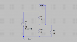
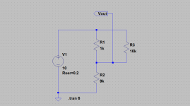
The first circuit below shows a pot (R1 + R2) in series with a load R3. To make the "pot" work when I increased R1 by 1K I would decrease R2 by 1k, etc., plotting 10 points from 0k to 10k. I did one set of plots for a 20k load (R12 and R13 reduced to 20K) and another set for a 10K load. The third set of plots shows the load returned to Vin rather than ground which would be useless for the O2, but shows how that configuration inverts the curve.
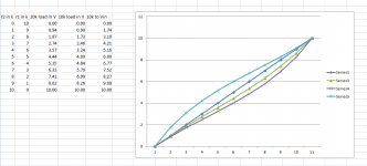
I then plotted the points, which can be compared with the Alps pot taper curve on bottom of page 359 of the datasheet here
http://www.alps.com/WebObjects/catalog.woa/E/PDF/Potentiometer/MetalShaft/RK097/RK097.PDF
From the graphs the 10k load is more-or-less similar to the 15A taper. None of the curves reproduce the 3B taper curve though that the original RK097122008T pot in the BOM has, as can be seen. Note that any of these tapers have the same endpoints (minimum volume of 0k and maximum volume of 10k) of course. The difference is just the shape of the curve between those two points.
So.. to summarize... the O2 pot could be replaced with a 10K linear taper
PTD902-2015K-B103 Bourns Potentiometers
http://www.bourns.com/data/global/pdfs/ptd90.pdf
and R12 and R13 replaced by 10K resistors to purposely load the pot and re-create an audio taper, while dropping the output offset voltage a bit. I couldn't find a suitable linear Alps pot - Alps only seems to have dual gang 10K in log tapers, except for one with a center detent - but Bourns did have a linear 10K here in their pro audio line.
Series 1 in the graph below is the value of R2 column, which is linear of course. The series 3 and series 4 graphs are the 3rd and 4th columns, the voltages across the 20k and 10k pots returned to ground (first circuit diagram) with 10Vdc coming in. 10V is roughly the peak input voltage to the pot with a 7Vrms signal output from the O2 first stage. The final graph, series 5, is the last column with 10K load now returned to Vin, as in the second circuit diagram.
Regal -
I was able to confirm the issue of lower R12/R13 values loading the pot. But flipping that around and doing it on purpose turns out to actually be worthy of another mod, so I'm writing this up that way.
As it turns out the coupling capacitor would make no difference on a reduced value R12/R13 loading the pot (vs. connecting the load resistor directly), at least between roughly 20Hz to 20kHz, since the capacitor is a short for all practical purposes at those frequencies. Conceptually just like connecting R12 or R13 to the pot directly. That means the lower value of R12 and R13 will affect the pot's taper curve, or how the resistance changes vs. rotation, the same as with a DC connection as far as the signal pass through is concerned. And as I remembered the effect is to convert a linear taper into more of a logarithmic (audio) taper.
But... flipping that around, a linear pot could actually be used on purpose in the O2 instead of the log pots specified in the BOM, and then "converted" into an audio taper by an even lower value of R12/R13. And those lower values would in turn produce even lower offset voltage numbers. Again, just a reminder here to anyone reading, lower offset voltage in the O2 is not needed in any way. The existing circuit already produces very low offset voltages. This is just messing around for modding fun.
I couldn't find a way to produce a variable resistor in LT Spice to simulate the setup. Instead I did it the old fashioned way of setting up a test circuit sim, changing the resistor values manually, and then plotting and graphing the points.
The first circuit below shows a pot (R1 + R2) in series with a load R3. To make the "pot" work when I increased R1 by 1K I would decrease R2 by 1k, etc., plotting 10 points from 0k to 10k. I did one set of plots for a 20k load (R12 and R13 reduced to 20K) and another set for a 10K load. The third set of plots shows the load returned to Vin rather than ground which would be useless for the O2, but shows how that configuration inverts the curve.
I then plotted the points, which can be compared with the Alps pot taper curve on bottom of page 359 of the datasheet here
http://www.alps.com/WebObjects/catalog.woa/E/PDF/Potentiometer/MetalShaft/RK097/RK097.PDF
From the graphs the 10k load is more-or-less similar to the 15A taper. None of the curves reproduce the 3B taper curve though that the original RK097122008T pot in the BOM has, as can be seen. Note that any of these tapers have the same endpoints (minimum volume of 0k and maximum volume of 10k) of course. The difference is just the shape of the curve between those two points.
So.. to summarize... the O2 pot could be replaced with a 10K linear taper
PTD902-2015K-B103 Bourns Potentiometers
http://www.bourns.com/data/global/pdfs/ptd90.pdf
and R12 and R13 replaced by 10K resistors to purposely load the pot and re-create an audio taper, while dropping the output offset voltage a bit. I couldn't find a suitable linear Alps pot - Alps only seems to have dual gang 10K in log tapers, except for one with a center detent - but Bourns did have a linear 10K here in their pro audio line.
Series 1 in the graph below is the value of R2 column, which is linear of course. The series 3 and series 4 graphs are the 3rd and 4th columns, the voltages across the 20k and 10k pots returned to ground (first circuit diagram) with 10Vdc coming in. 10V is roughly the peak input voltage to the pot with a 7Vrms signal output from the O2 first stage. The final graph, series 5, is the last column with 10K load now returned to Vin, as in the second circuit diagram.
Attachments
Last edited:
O2 +/-18V rail LME49860 600R headphone mod
After just posting an 18-20V power supply rail mod for the Wire amp, specifically with hard-to-drive 600R headphone models, I realized that a similar thing would work for the O2, so here goes.
The secret is that the higher impedance 600 ohm headphone load draws significantly less current. The amp really doesn't need much, if any, current buffer anymore for such a high impedance load. A single chip LME49860 CMOY would almost do the job. In other words, what is needed is more voltage rather than more current in this case. Another enabling factor is the LME49860 being unity-gain stable, so it can also be wired for the parallel output buffers in the O2 as well as the first stage gain chip.
A safety note up front. Best not to try this with less than 600 ohm headphones or a person stands a real chance of damaging their headphones if the volume were to be turned way up. And even with 600 ohm headphones this mod would be completely unneeded for moderate to good sensitivity headphones. It is just that magic hard-to-drive combination of 600 ohm and low sensitivity that this mod may have some value for.
The mod raises the power supply rails to +/-18v, replaces the NJM2068 and NJM4556 chips with higher voltage LME49860 dual low-distortion audio op amps (rated to 44V maximum, = +/-22V rails max) and the NJM2093D comparator with a higher voltage (40V maximum) LT1018 dual comparator. Here are the spec sheets for these parts:
http://www.national.com/ds/LM/LME49860.pdf
LME49860NA/NOPB National Semiconductor (TI) Op Amps
http://www.datasheetcatalog.org/datasheet/lineartechnology/10178fc.pdf
Digi-Key - LT1018CN8#PBF-ND (Manufacturer - LT1018CN8#PBF)
Here are the specific changes for this mod.
Power supply-
The power transformer is replaced with a 20VAC 500mA unit:
WAU20-500 Triad Magnetics Plug-In AC Adapters
and the voltage regulators with fixed +/-18v types:
MC7818CTG ON Semiconductor Linear Regulators - Standard
MC7918CTG ON Semiconductor Linear Regulators - Standard
The batteries should either be left out altogether to make it a desktop-only unit, or 6.2V 500mW zener diodes should be put in series with R1 and R2 to keep the charging parameters the same as the original. But in that case, when on battery, voltage to the amp is still just at +/-8.4V, of course from the batteries.
It maybe possible to get 4 of the 8.4V "9v" NiMH cells in the battery area by notching out the PC board under the batteries and using the taller B3-080 case. At least the mechanical measurements say it should work. That would allow two batteries in series on each rail for a total of +/-16.8Vdc rails while on batteries. But that is a mod for another day.
Power Management -
The NJM2903D (U2) dual comparator is replaced with the higher voltage LT1018.
The current through the reference LED D7 will increase with +/18V rails but it is still well within specs. I'm not changing R6 so that the circuit will still work correctly with +/-8.4V batteries. The LT1018 includes a pullup resistor that may eliminate the need for R4, but I'm leaving it in for now.
22V 500mW zener diodes need to be placed across C16 and C21 to clamp the Vgs at 22V, otherwise the new +36V between the rails would exceed Vgs(max) for any of the BOM mosfets.
C1 needs to be increased to a 50v unit.
Signal Path -
The NJM2068 (U1) and the NJM4556s (U3, U4) are all replaced with LME49860 DIP-8 chips.
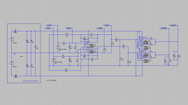
The gain resistors may need to be increased to take advantage of the new 14V maximum swing available. In the simulation below a 240R gain resistor with a 2Vpeak input signal (1.4Vrms) resulted in a 14Vpeak output (9.9Vrms) into 600 ohms.
I've tried replacing U1-U4 with the LT1018 and LME49860 chips with the regular +/-12V rails just now, so I know that much works OK for certain. I'll have to swap out the regulators and get in the 20V transformer to actually test things at +/-18V rails - so for now the higher +/-18v rails here are untested. Builder beware!
As for performance, the measurements for this mod shouldn't be any worse than the stock O2, and actually stand a chance of being just a tiny bit better (into 600 ohms ONLY!). The LME49860 chip shows either the same numbers or very slight improvements in all areas over the NJM2068 and NJM4556 chips. However, as RocketScientist has pointed out many times, the NJM chips are around 50 cents each while this chip is $4 a pop! But the main reason a very slight improvement may be had is that the output chips are also LME49860s. As RocketScientist has said, the NJM4556 output chips are really the limiting factor on one or more of the measured parameters, meaning just changing out the first stage gain chip alone isn't likely to improve anything regardless of how "good" that chip is. The NJM4556's are a slight trade-off for current capability. That wouldn't be the case here.
Again, good time to re-iterate, this mod only has use with 600 ohm hard-to-drive headphones. Any lower impedance headphone could be severely damaged if the volume were turned up and it was hit with the higher voltage available with this mod. So there is no performance improvement to be had here in general, just possibly some amount so small that it would only show up on RocketScientist's equipment (probably not even audible) and then only for 600R phones.
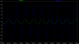
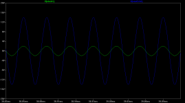
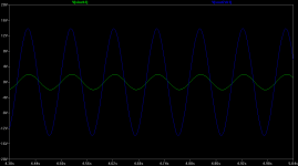
Sim results below. 14.0V is the highest output voltage swing before the chips clip into 600 ohms in parallel with 390pF (cable capacitance). 14v peak is only 14v / 600R = 23mA, which would actually be within the 28mA current capability of just one LME49860 chip, according to the datasheet. A person could do this whole thing as just a single chip CMOY! keeping the separate output design in the O2 though allows the use of the volume pot in the middle with the associated benefits. Since each output chip is in parallel with the O2 that is only 11.5mA through each half section of the output LME49860s, well within specifications.
The green is the 2V peak input signal and the blue the 14V peak output. The first plot is 2.5kHz, the second 25kHz and the third 10Hz.
After just posting an 18-20V power supply rail mod for the Wire amp, specifically with hard-to-drive 600R headphone models, I realized that a similar thing would work for the O2, so here goes.
The secret is that the higher impedance 600 ohm headphone load draws significantly less current. The amp really doesn't need much, if any, current buffer anymore for such a high impedance load. A single chip LME49860 CMOY would almost do the job. In other words, what is needed is more voltage rather than more current in this case. Another enabling factor is the LME49860 being unity-gain stable, so it can also be wired for the parallel output buffers in the O2 as well as the first stage gain chip.
A safety note up front. Best not to try this with less than 600 ohm headphones or a person stands a real chance of damaging their headphones if the volume were to be turned way up. And even with 600 ohm headphones this mod would be completely unneeded for moderate to good sensitivity headphones. It is just that magic hard-to-drive combination of 600 ohm and low sensitivity that this mod may have some value for.
The mod raises the power supply rails to +/-18v, replaces the NJM2068 and NJM4556 chips with higher voltage LME49860 dual low-distortion audio op amps (rated to 44V maximum, = +/-22V rails max) and the NJM2093D comparator with a higher voltage (40V maximum) LT1018 dual comparator. Here are the spec sheets for these parts:
http://www.national.com/ds/LM/LME49860.pdf
LME49860NA/NOPB National Semiconductor (TI) Op Amps
http://www.datasheetcatalog.org/datasheet/lineartechnology/10178fc.pdf
Digi-Key - LT1018CN8#PBF-ND (Manufacturer - LT1018CN8#PBF)
Here are the specific changes for this mod.
Power supply-
The power transformer is replaced with a 20VAC 500mA unit:
WAU20-500 Triad Magnetics Plug-In AC Adapters
and the voltage regulators with fixed +/-18v types:
MC7818CTG ON Semiconductor Linear Regulators - Standard
MC7918CTG ON Semiconductor Linear Regulators - Standard
The batteries should either be left out altogether to make it a desktop-only unit, or 6.2V 500mW zener diodes should be put in series with R1 and R2 to keep the charging parameters the same as the original. But in that case, when on battery, voltage to the amp is still just at +/-8.4V, of course from the batteries.
It maybe possible to get 4 of the 8.4V "9v" NiMH cells in the battery area by notching out the PC board under the batteries and using the taller B3-080 case. At least the mechanical measurements say it should work. That would allow two batteries in series on each rail for a total of +/-16.8Vdc rails while on batteries. But that is a mod for another day.
Power Management -
The NJM2903D (U2) dual comparator is replaced with the higher voltage LT1018.
The current through the reference LED D7 will increase with +/18V rails but it is still well within specs. I'm not changing R6 so that the circuit will still work correctly with +/-8.4V batteries. The LT1018 includes a pullup resistor that may eliminate the need for R4, but I'm leaving it in for now.
22V 500mW zener diodes need to be placed across C16 and C21 to clamp the Vgs at 22V, otherwise the new +36V between the rails would exceed Vgs(max) for any of the BOM mosfets.
C1 needs to be increased to a 50v unit.
Signal Path -
The NJM2068 (U1) and the NJM4556s (U3, U4) are all replaced with LME49860 DIP-8 chips.
The gain resistors may need to be increased to take advantage of the new 14V maximum swing available. In the simulation below a 240R gain resistor with a 2Vpeak input signal (1.4Vrms) resulted in a 14Vpeak output (9.9Vrms) into 600 ohms.
I've tried replacing U1-U4 with the LT1018 and LME49860 chips with the regular +/-12V rails just now, so I know that much works OK for certain.
I'll have to swap out the regulators and get in the 20V transformer to actually test things at +/-18V rails - so for now the higher +/-18v rails here are untested. Builder beware!As for performance, the measurements for this mod shouldn't be any worse than the stock O2, and actually stand a chance of being just a tiny bit better (into 600 ohms ONLY!). The LME49860 chip shows either the same numbers or very slight improvements in all areas over the NJM2068 and NJM4556 chips. However, as RocketScientist has pointed out many times, the NJM chips are around 50 cents each while this chip is $4 a pop! But the main reason a very slight improvement may be had is that the output chips are also LME49860s. As RocketScientist has said, the NJM4556 output chips are really the limiting factor on one or more of the measured parameters, meaning just changing out the first stage gain chip alone isn't likely to improve anything regardless of how "good" that chip is. The NJM4556's are a slight trade-off for current capability. That wouldn't be the case here.
Again, good time to re-iterate, this mod only has use with 600 ohm hard-to-drive headphones. Any lower impedance headphone could be severely damaged if the volume were turned up and it was hit with the higher voltage available with this mod. So there is no performance improvement to be had here in general, just possibly some amount so small that it would only show up on RocketScientist's equipment (probably not even audible) and then only for 600R phones.
Sim results below. 14.0V is the highest output voltage swing before the chips clip into 600 ohms in parallel with 390pF (cable capacitance). 14v peak is only 14v / 600R = 23mA, which would actually be within the 28mA current capability of just one LME49860 chip, according to the datasheet. A person could do this whole thing as just a single chip CMOY! keeping the separate output design in the O2 though allows the use of the volume pot in the middle with the associated benefits. Since each output chip is in parallel with the O2 that is only 11.5mA through each half section of the output LME49860s, well within specifications.
The green is the 2V peak input signal and the blue the 14V peak output. The first plot is 2.5kHz, the second 25kHz and the third 10Hz.
Attachments
Last edited:
After just posting an 18-20V power supply rail mod for the Wire amp, specifically with hard-to-drive 600R headphone models, I realized that a similar thing would work for the O2, so here goes.
.
Thanks very much I was working on the same mod, but was planning on experimenting with using voltage dividers to protect Q1 & Q2 since the zeners would allow a situation with great DC offset (say rails were +30V & -36V), but the odds are slim and the zeners would probably be 100%.
The opamp changes I hadn't gotten to, thankyou for the recommendations. I have the 20V wallwart, but I may go with +-15V, it may be enough to drive the 600 ohm AKG's sufficiently.
The Mouser part for the 50V C2&C3 of same dimensions and ripple as the BOM 35V cap is UVK1H471MPD.
As far as R6, I think it best to up it to 63k, this LED is run in a pretty non-linear area, this just takes that risk out.
Can you explain one thing on the opamp power dissipation? If one only has Grados (low current, low voltage, low impedance) and 600 ohm 200mW AKGs, but not the high current low efficient low ohm phones, wouldn't the original opamps be OK as far as dissipation at +-15V ?
Thanks again, and I will update on how things go.
regal- thanks for the comments!
You are right, a voltage divider to protect the mosfet gates works too, and is probably a better solution. I think RocketScientist had even mentioned that once months ago when I was asking some questions about the mosfet Vgs. That would avoid any noise generation by the zeners too.
15vac or 16vac power adapters may do the job, especially given the low current draw of the high impedance phones. The minimum dropout voltage across the voltage regulators should decrease with decreasing current. If you have access to a scope just take a look at the input sawtooth wave (to the regulators), and if your minimum trough is at least 13.5V or so (13 may even do the job) then things should work OK.
You would probably be OK with the 35v C2 - C5. Even with 20VAC secondary that would give a max of {[20vac - (0.7V diode drop)] * sqrt(2)} = 27.3Vdc. Add a 15% line voltage fluctuation and it still is only up to 31V. The voltage regulators are also 35Vdc max input, so the amp has bigger trouble if the input voltage to the regs goes above 35!
I agree about R6. Best to make that change.
You should be OK with the original NJM chips at +/-15V rails with the 600 ohm AKGs at least. Assuming the voltage overhead of the NJM4556 chips is about 2.5V, 15V rails should result in a 12.5V maximum swing, which would be 8.84Vrms. Into 600 ohms that would be (8.84V ^ 2) / 600R = 120mW. The rms current would be 8.84V / 600R = 14.7mA. The chip dissipation should be the difference between the input from rails and the load, or (12V - 8.84) * 0.0147A = 46mW. The 4556 will do 700mW max, or more likely de-rated to around 400mW without a heatsink and inside the higher temperature ambient inside the case. The maximum dissipation point of the load may not be the maximum point with the chip, though. Here are a few more data points of output voltage vs. chip dissipation at 600R and +/-15V rails:
8.0V 53mW
7.0V 58mW
6.0V 60mW
5.0V 58mW
4.0V 53mW
all well within bounds, at least unless I've mucked something up with the math.
Now if you were running +/-18V rails using the LME49860 chips, lets assume a 3V overhead on the chip. That would give 15vdc maximum swing, which is 10.6Vrms and 17.7mA rms current through the load. That gives 187mW into the 600R AKGs, closer to that 200mW max. As for the LME49860 chip it would have (15V - 10.6) * 17.7mA = 78mW dissipation at the maximum headphone load dissipation point. Completing a table as above for the chip dissipation gives a maximum chip power dissipation point of around 93mW at 7.5Vrms into the load. The LME49860 has similar dissipation limits to the NJM4556 - all the DIP8 form factors pretty much do, it seems - so this would also be well within bounds.
I've left the voltage drop and dissipation in the output 1R resistors out in all the calculations above since it is so insignificant next to the 600 ohm headphone load.
What model of Grados do you have in mind?
Last edited:
For the Grados they are 32 ohm (Magnums), Usually listen at .2V-.to max .4V rms. So that would be .4/32=12.5ma. Chip dissipation would be 12 - .4 (lets round it to 12V)*12.5ma = 150 mw.
That's why I was confused with the datasheet saying 700mW, but you are right about how we should de-rate that number.
I bought a couple of the heavy stick on Dip16 heatsinks on Mouser that I am planning to cut in half. So I was thinking I'd be OK. But the case is damn small. If the board had standoff holes I would have bought a bigger case, but I bought a few of the opamps, and plan on letting it run with a 30 ohm resistor load, see how hot it gets.
I'll post my results here.
Thanks much for the info.
Oh also as far as the zener noise, I'm thinking the big caps should kill most of their noise if one choses that route. May also just forgo the "power" managment and use an e12.
Hope RS isn't offended, the design is perfect as is but we all like to tinker
Edit: Also I almost think the CRC mod is mandatory with 20VAC wallwart as far as the 35V max input to the voltage regulators, I am surprised folks haven't had trouble with that.
Last edited:
regal -
Definitely post your results of the mod build! I would encourage anybody doing any of these mods to post results and pictures too - whether it works or not. Post a picture of the smoldering remains if that is all that is left afterward, lol!
The whole thing about using +/-15v rails with 32 ohm headphones is pretty interesting. True that the amp would not need to be turned up very much (volume) to get an acceptable sound level out of the phones. But the problem comes in what if the volume does get turned way up - then you get a large voltage swing into the small impedance load and the resultant power could be more than the headphones can handle, if the amp can source a lot of current.
Now a person might think "but that would never happen - I would never be turning the volume up loud enough to cause too much power to the headphones since it would be too loud". But here is a scenario that keeps sticking in my head. Lets say someone has a pair of 600 ohm low-sensitivity headphones that really do need the full 8.5Vrms-ot-so output swing from +/-15v rails to be loud enough. They are listing to their amp that way one evening and eventually switch it off and unplug the phones.
Then two days later they plug in a pair of 32 ohm headphones, which are still lying on the table and can't be heard yet, then switch the amp on, not really remembering where the volume control was last at or which of the two pairs of headphones it was last used with. And just as the amp is switched on the doorbell rings and the person has to run off for 10 minutes. When they come back they find the amp has been pumping out 8.5Vrms into the 32 ohm phones and they are now cooked. Could happen! Just replace "doorbell" with the phone ringing, the cat chucking up a hairball on the furniture, or any other unplanned distraction.
However in the particular case of using the LME49860s they are only capable of about 30mA each, or 60mA in parallel in the O2, which would limit maximum current (over the two NJM4556s which together can do around 140mA). The problem there (with the LME49860s) is that the result, with volume turned up, would be severe clipping going into the headphones. Not good.
So, to summarize, with +/-15Vdc rails even if the output chip dissipation would be within bounds for lower impedance headphones (with their lower voltage swing requirements) I really can't recommend using the modded amp with anything less than 600 ohn headphones. Just too easy to essentially make a mistake with the volume control and feed to much voltage to lower impedance headphones.
One solution here, when powering both a 32ohm and 600 low low-sensitivity set of headphones, is just to make two O2s. One built up the standard way with the 12V rails - or even 9V or 6V rails for safety! - for the 32 ohm headphones. Then a second O2 modded with 15V or 18 volt rails for the 600 ohm cans. There is just too much variation in headphone impedances, it seems, for one amp to cover all bases and still be "safe" from volume control accidents. One of my suggestions to RocketScientist along the way for the desktop O2 was a variable rail voltage control for this very reason, but that wouldn't really solve the "accident" problem either. It would be just as easy to have the rail voltage control in the wrong position when the doorbell rang.
Anyway, just my two cents!
I just realized that I never posted a link to the DIP8 heatsinks I used in the first set of mods in this thread. Here they are:
580100B00000G - Board level heatsinks
https://avnetexpress.avnet.com/stor...=500201&langId=-1&storeId=500201&listIndex=-1
I bought mine at Avnet Express and it looks like Newark also has them. Unfortunately Mouser and Digikey don't. The heatsinks worked out very well. I had to just bend one heatsink fin up slightly to avoid a 470uF cap and trim 1/16 off the bottom of the clip to clear a 0.22 cap. I'm going to eventually hot glue that bent fin right to the cap for even more mechanical support.
These heatsinks really work well, too! Fairly warm when I put a finger on them, indicating good thermal transfer from the chip.
I saw your post about the standoffs in the O2 thread. Yes, that would be an interesting way to go. Using a bigger case and mount with standoffs.
The AMB e12 is definitely a great little protection board! But by way of full disclosure I had a small amount of input on the latest version so I'm probably somewhat biased, too.
The ε12 Muting / Protect Circuit and the "history" link on the left...
But seriously that is a very good protection board and it senses actual DC riding on the output signal. AMB has some really good stuff.
The CRC filter is an interesting thing. My main purpose for it was filtering out power line noise that might happen to be in the upper audio band. Unfortunately the filter caps are around 20 times too small to filter out the 120hz and 180hz power line harmonics. The filter would have some value for power line noise from around 2khz on up that might happen to make it through the transformer via core or winding parasitics.
But the CRC filter has that voltage drop across the resistor and a reduction in ripple going into the regulator, both of which would reduce the regulator input voltage and make them run a bit cooler. I've seen a post or two on Head-Fi where folks seem to be using the filter mainly for that reason. Like you say, not a bad idea for 20VAC input to knock the voltage down a bit before it hits the regulators. I just noticed this morning that RocketScientist has added a mod in the O2 thread that puts a 10-15R resistor in series with the rectifier diodes to do a similar thing, although putting it betwen the caps here gives some filtering too - but is much more of a DIY project, having to cut traces and all!
I'll be quite curious to hear how your +/-15V mod does with your 600R cans, if you decide to build it!
Definitely post your results of the mod build! I would encourage anybody doing any of these mods to post results and pictures too - whether it works or not. Post a picture of the smoldering remains if that is all that is left afterward, lol!
The whole thing about using +/-15v rails with 32 ohm headphones is pretty interesting. True that the amp would not need to be turned up very much (volume) to get an acceptable sound level out of the phones. But the problem comes in what if the volume does get turned way up - then you get a large voltage swing into the small impedance load and the resultant power could be more than the headphones can handle, if the amp can source a lot of current.
Now a person might think "but that would never happen - I would never be turning the volume up loud enough to cause too much power to the headphones since it would be too loud". But here is a scenario that keeps sticking in my head. Lets say someone has a pair of 600 ohm low-sensitivity headphones that really do need the full 8.5Vrms-ot-so output swing from +/-15v rails to be loud enough. They are listing to their amp that way one evening and eventually switch it off and unplug the phones.
Then two days later they plug in a pair of 32 ohm headphones, which are still lying on the table and can't be heard yet, then switch the amp on, not really remembering where the volume control was last at or which of the two pairs of headphones it was last used with. And just as the amp is switched on the doorbell rings and the person has to run off for 10 minutes. When they come back they find the amp has been pumping out 8.5Vrms into the 32 ohm phones and they are now cooked.
Could happen! Just replace "doorbell" with the phone ringing, the cat chucking up a hairball on the furniture, or any other unplanned distraction. However in the particular case of using the LME49860s they are only capable of about 30mA each, or 60mA in parallel in the O2, which would limit maximum current (over the two NJM4556s which together can do around 140mA). The problem there (with the LME49860s) is that the result, with volume turned up, would be severe clipping going into the headphones. Not good.
So, to summarize, with +/-15Vdc rails even if the output chip dissipation would be within bounds for lower impedance headphones (with their lower voltage swing requirements) I really can't recommend using the modded amp with anything less than 600 ohn headphones. Just too easy to essentially make a mistake with the volume control and feed to much voltage to lower impedance headphones.
One solution here, when powering both a 32ohm and 600 low low-sensitivity set of headphones, is just to make two O2s. One built up the standard way with the 12V rails - or even 9V or 6V rails for safety! - for the 32 ohm headphones. Then a second O2 modded with 15V or 18 volt rails for the 600 ohm cans. There is just too much variation in headphone impedances, it seems, for one amp to cover all bases and still be "safe" from volume control accidents. One of my suggestions to RocketScientist along the way for the desktop O2 was a variable rail voltage control for this very reason, but that wouldn't really solve the "accident" problem either. It would be just as easy to have the rail voltage control in the wrong position when the doorbell rang.
Anyway, just my two cents!
I just realized that I never posted a link to the DIP8 heatsinks I used in the first set of mods in this thread. Here they are:
580100B00000G - Board level heatsinks
https://avnetexpress.avnet.com/stor...=500201&langId=-1&storeId=500201&listIndex=-1
I bought mine at Avnet Express and it looks like Newark also has them. Unfortunately Mouser and Digikey don't. The heatsinks worked out very well. I had to just bend one heatsink fin up slightly to avoid a 470uF cap and trim 1/16 off the bottom of the clip to clear a 0.22 cap. I'm going to eventually hot glue that bent fin right to the cap for even more mechanical support.
These heatsinks really work well, too! Fairly warm when I put a finger on them, indicating good thermal transfer from the chip.
I saw your post about the standoffs in the O2 thread. Yes, that would be an interesting way to go. Using a bigger case and mount with standoffs.
The AMB e12 is definitely a great little protection board! But by way of full disclosure I had a small amount of input on the latest version so I'm probably somewhat biased, too.
The ε12 Muting / Protect Circuit and the "history" link on the left...
But seriously that is a very good protection board and it senses actual DC riding on the output signal. AMB has some really good stuff.
The CRC filter is an interesting thing. My main purpose for it was filtering out power line noise that might happen to be in the upper audio band. Unfortunately the filter caps are around 20 times too small to filter out the 120hz and 180hz power line harmonics. The filter would have some value for power line noise from around 2khz on up that might happen to make it through the transformer via core or winding parasitics.
But the CRC filter has that voltage drop across the resistor and a reduction in ripple going into the regulator, both of which would reduce the regulator input voltage and make them run a bit cooler. I've seen a post or two on Head-Fi where folks seem to be using the filter mainly for that reason. Like you say, not a bad idea for 20VAC input to knock the voltage down a bit before it hits the regulators. I just noticed this morning that RocketScientist has added a mod in the O2 thread that puts a 10-15R resistor in series with the rectifier diodes to do a similar thing, although putting it betwen the caps here gives some filtering too - but is much more of a DIY project, having to cut traces and all!
I'll be quite curious to hear how your +/-15V mod does with your 600R cans, if you decide to build it!
Last edited:
regal -
. When they come back they find the amp has been pumping out 8.5Vrms into the 32 ohm phones and they are now cooked.
!
All the new high power commercial amps have this issue, Heck even the B22 which folks have been using for years.
So much for "harmless" excess I suppose!
Its not an issue if you are on old timer, we always turn the amp down all the way when changing phones. Not doing that would be like walking under a ladder
Its not an issue if you are on old timer, we always turn the amp down all the way when changing phones. Not doing that would be like walking under a ladder
Exactly!
That would solve the problem. I know that AMB keeps mentioning turning the volume all the way down between headphone changes over on his forum, for any of the amps. Also solves the issue of TRS plugs shorting on their way in and out.regal - I've discovered what could be another hiccup in using the higher voltage +/-15V or +/-18V rails with lower headphone impedances. In your example of the 32R Grados needing a maximum output swing of 0.4Vrms, even if the chip dissipation were OK at that level (they probably are) and even if the volume control were turned fully down between headphone changes, the volume control rotation would be only about 1/20th of full rotation. Probably too small to be practically set. The problem is that the first stage would still have to have a gain of 7x-or-so to produce the output voltage swing needed for the 600R phones. So the first stage output would be the 8.84Vrms (15V rails) or 10.6 (18Vrms rails) and only 0.4V is needed.
One possible solution is set the gain switch up so that high gain is 7x for the 600R headphones and low gain is the 1x minimum for the 32R phones. But even then the maximum rotation would only be 1/4, or less with the non-linear tapers in the BOM. But at least that would probably be usable. There is probably also some clever way around the pot rotation issue too out there somewhere.
I think that I'm still a fan of two separate O2s. The +/-15V or +/-18V O2 for the 600R phones, and a stock +/-12V, or even down to +/-9V or +/-6V O2 for the 32R phones.
One possible solution is set the gain switch up so that high gain is 7x for the 600R headphones and low gain is the 1x minimum for the 32R phones. But even then the maximum rotation would only be 1/4, or less with the non-linear tapers in the BOM. But at least that would probably be usable. There is probably also some clever way around the pot rotation issue too out there somewhere.
I think that I'm still a fan of two separate O2s.
The +/-15V or +/-18V O2 for the 600R phones, and a stock +/-12V, or even down to +/-9V or +/-6V O2 for the 32R phones.+/-15V and +/-18V revised chip dissipation calculations
I just realized that I did, in fact, muck up the output chip power dissipation calculations for the 600R headphones with +/-15 V rails (NJM4556 chips) and +/-18V rails (LME49860 chips), in a post above. My wording was right, input power from the rails minus the power delivered to the headphones (and 1R resistor dissipation), but then my power dissipation calculations went in an odd direction using maximum chip voltage swing.
Here are the corrected calculations. The output chip dissipation roughly doubles from what I posted above, but is still well within bounds for either case.
For the NJM4556 chips running +/-15V rails into 600R headphones the maximum swing is still 8.84Vrms and the corresponding maximum rms current 14.7mA, as I posted earlier. But it is important to be a bit more precise that 8.84Vrms is the output of the O2 into the headphones, ie after the 1R resistors. The total power dissipation in the 1R resistors would then be (14.7mA * 0.5R) = 7.35mW.
The NJM4556 power dissipation at the maximum output voltage swing would then be P(rail) – P(1R resistors) – P(headphone) = (15V * 14.7mA) – 7.35mW – 120mW = 93.1mW. Still well within even the de-rated 400mW power handling capability of the NJM4556 chip. A double-check on peak current delivery is also in order. I(peak) would be (12.5v [peak output voltage swing]) / 600R = 20.8mA, well within the 140mA capability of the two paralleled chip halves. I haven't done the math, but at just 93mW chip dissipation at full output voltage swing I would guess that 300R headphones may also fall within chip dissipation limits with +/-15V rails.
For the LME49860 chips running +/-18V rails into 600R headphones the maximum swing is still 10.6Vrms and the corresponding maximum rms current 17.7mA, as I posted earlier. The 10.6Vrms is again after the 1R resistors into the headphone load. The total power dissipation in the 1R resistors would then be (17.7mA * 0.5R) = 8.85mW.
The LME49860 power dissipation at the maximum output voltage swing would then be P(rail) – P(1R resistors) – P(headphone) = (18V * 17.7mA) – 8.85mW – 187mW = 123mW. Also still well within even the de-rated 400mW power handling capability of the LME49860 chip. A double-check on peak current delivery again: I(peak) would be (15.0v [peak output voltage swing]) / 600R = 25mA. That is 25mA total over the two paralleled op amp sections, or 12.5mA per section, well within the data sheet maximum of 26mA. Again, given these numbers, I would say there is a good chance that 300R phones may also be within chip dissipation and peak current limits at +/-18V rails.
regal - I've discovered what could be another hiccup in using the higher voltage +/-15V or +/-18V rails with lower headphone impedances. In your example of the 32R Grados needing a maximum output swing of 0.4Vrms, even if the chip dissipation were OK at that level (they probably are) and even if the volume control were turned fully down between headphone changes, the volume control rotation would be only about 1/20th of full rotation. Probably too small to be practically set. The problem is that the first stage would still have to have a gain of 7x-or-so to produce the output voltage swing needed for the 600R phones. So the first stage output would be the 8.84Vrms (15V rails) or 10.6 (18Vrms rails) and only 0.4V is needed.
One possible solution is set the gain switch up so that high gain is 7x for the 600R headphones and low gain is the 1x minimum for the 32R phones. But even then the maximum rotation would only be 1/4, or less with the non-linear tapers in the BOM. But at least that would probably be usable. There is probably also some clever way around the pot rotation issue too out there somewhere.
I think that I'm still a fan of two separate O2s.
Thanks again for the info. I know Grados are commonly used with amplifiers that have a gain as high as 8x or more with the same series of alps pots (I think), the 1x should be fine, but you are right that ideally one would make an O2 for the low impedance cans separate/dedicated.
The smart thing to do with the 1x gain would be to eliminate the first opamp gain stage all together, all it is doing is adding noise and distortion to headphones like Grados that max out at .5Vrms (assuming a normal 2vrms source.) Really only need the buffer section of the O2 for these phones.
The smart thing to do with the 1x gain would be to eliminate the first opamp gain stage all together, all it is doing is adding noise and distortion to headphones like Grados that max out at .5Vrms (assuming a normal 2vrms source.) Really only need the buffer section of the O2 for these phones.
I agree! That is a good idea. All the first stage parts between the 220pF RF filter capacitors and the pot could be left out, including the 10K input resistor. Just jumper the 220pF cap right over to that channel's pot. The 10k pot then becomes the "input resistor" and the RF filter still works as before. The O2 signal path then reduces to the typical pot-in-front design feeding the second stage current buffer. The second stage still has the input current blocking capacitors, so still no DC through the pot. The only thing lost is gain, which like you say just isn't needed if someone knows upfront that they only need 1x.
Good stuff!
O2 amp - DC power jack mod for battery charging only
I'm posting this reply from the O2 thread here so as not to muck up RocketScientist's thread with modifications.
I should also note right up front that this project may not buy a whole lot over simply using the WAU12-200 AC adapter for the O2 that RocketScientist has specified in the BOM. That adapter is about the same size as most 24Vdc 100mA adapters. If all you are doing is charging the batteries it has plenty of power.
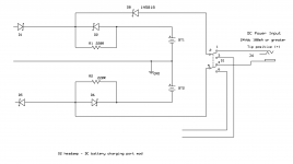
Here is one way to do it, although RocketScientist may have a slicker way. A DC input jack (J4) and Schottky diode (D8) could be connected as shown below to the unused pins 1 and 4 on the power switch, then fed with a DC adapter that is 24Vdc and at least 100mA capable. The adapter should be 24Vdc only - rated nothing higher or lower. This arrangement works for charging the batteries - your request - but would not run the amp to produce sound. You can get to the unused pins 1 and 4 on the power switch underneath the O2 PCB, then run the wires back up through one of the PCB holes if you need to wherever you intend to mount the DC jack.
Here are the details. This one is essentially a modification. This mod works because the DPDT power switch that RocketScientist specified is non-shorting, meaning that it breaks the connection to the rest of the O2 (power management circuit and signal path) before making the connection to the single-rail DC adapter. Since there is no ground wire coming in from the power source in this case (not a dual rail power adaptor) there would be no way to run the rest of the O2 properly, so the rest of the circuitry has to be switched out like this.
Then Maha Powerex tech support tells me that it is OK to charge two 8.4V NiMH cell in series like this if the charging currents are limited to essentially trickle rates, which is what the two 220 ohm resistors R1 and R2 that RocketScientist have in the circuit do. In this arrangement the power flows from the DC jack around the reverse-biased D2 and D6, through the 220R resistors to the batteries, just exactly as happens from the O2's voltage regulators when those are used on AC.
In this case through instead of 12Vdc across each battery individually with each having a 220R current limiter, we are applying 24Vdc across both batteries in series and using two 220Rs in series to limit the current. Equivalent circuits either way. The ground no longer works, or is used, but it doesn't matter just for charging in this arrangement.
D1 and D5 are reversed biased in this setup and block current flow back into the voltage regulator circuits. A new Schottky diode D8 is added to prevent current flow from the voltage regulators back to the DC adapter under a special circumstance. The issue here is that if both voltage regulators were at the high end of their specifications, +12.2V and -12.2V, that would give 24.4Vdc from negative to positive rail on the input side of D1 and D5. Minus the 0.2V Schottky drop that leaves 24Vdc on the other side of D1 and D5. If the DC adapter were then less than this, such as 23.6Vdc, current would flow from the O2 voltage regulators into the DC adapter.
So with D8 added it doesn't matter if the AC adapter is plugged in or not when the DC adaptor is plugged in. The Schottky diodes will figure it out. If the O2 voltage regulators produce a higher voltage they will be used to charge the batteries. Otherwise the DC adaptor will will win (which should be the case with the vast majority of "24Vdc" adapters from my experience, they usually run at 24.5Vdc - 28Vdc) and charge the batteries.
Please post a picture if you build it!
Would it be possible to feed the amp with DC, mainly to charge the batteries. I don't mean necessary on the onboard AC connector, I could tap someware and add an extra DC input.
I'm posting this reply from the O2 thread here so as not to muck up RocketScientist's thread with modifications.
I should also note right up front that this project may not buy a whole lot over simply using the WAU12-200 AC adapter for the O2 that RocketScientist has specified in the BOM. That adapter is about the same size as most 24Vdc 100mA adapters. If all you are doing is charging the batteries it has plenty of power.
Here is one way to do it, although RocketScientist may have a slicker way.
A DC input jack (J4) and Schottky diode (D8) could be connected as shown below to the unused pins 1 and 4 on the power switch, then fed with a DC adapter that is 24Vdc and at least 100mA capable. The adapter should be 24Vdc only - rated nothing higher or lower. This arrangement works for charging the batteries - your request - but would not run the amp to produce sound. You can get to the unused pins 1 and 4 on the power switch underneath the O2 PCB, then run the wires back up through one of the PCB holes if you need to wherever you intend to mount the DC jack.Here are the details. This one is essentially a modification.
This mod works because the DPDT power switch that RocketScientist specified is non-shorting, meaning that it breaks the connection to the rest of the O2 (power management circuit and signal path) before making the connection to the single-rail DC adapter. Since there is no ground wire coming in from the power source in this case (not a dual rail power adaptor) there would be no way to run the rest of the O2 properly, so the rest of the circuitry has to be switched out like this.Then Maha Powerex tech support tells me that it is OK to charge two 8.4V NiMH cell in series like this if the charging currents are limited to essentially trickle rates, which is what the two 220 ohm resistors R1 and R2 that RocketScientist have in the circuit do. In this arrangement the power flows from the DC jack around the reverse-biased D2 and D6, through the 220R resistors to the batteries, just exactly as happens from the O2's voltage regulators when those are used on AC.
In this case through instead of 12Vdc across each battery individually with each having a 220R current limiter, we are applying 24Vdc across both batteries in series and using two 220Rs in series to limit the current. Equivalent circuits either way. The ground no longer works, or is used, but it doesn't matter just for charging in this arrangement.
D1 and D5 are reversed biased in this setup and block current flow back into the voltage regulator circuits. A new Schottky diode D8 is added to prevent current flow from the voltage regulators back to the DC adapter under a special circumstance. The issue here is that if both voltage regulators were at the high end of their specifications, +12.2V and -12.2V, that would give 24.4Vdc from negative to positive rail on the input side of D1 and D5. Minus the 0.2V Schottky drop that leaves 24Vdc on the other side of D1 and D5. If the DC adapter were then less than this, such as 23.6Vdc, current would flow from the O2 voltage regulators into the DC adapter.
So with D8 added it doesn't matter if the AC adapter is plugged in or not when the DC adaptor is plugged in. The Schottky diodes will figure it out.
If the O2 voltage regulators produce a higher voltage they will be used to charge the batteries. Otherwise the DC adaptor will will win (which should be the case with the vast majority of "24Vdc" adapters from my experience, they usually run at 24.5Vdc - 28Vdc) and charge the batteries.Please post a picture if you build it!
Attachments
Last edited:
- Status
- This old topic is closed. If you want to reopen this topic, contact a moderator using the "Report Post" button.
- Home
- Amplifiers
- Headphone Systems
- O2 amp CRC, diode, cap, and heatsink mods