I need to build a great amp for my Stax electrostatic headphones. There are a number of DIY designs, several of them by Kevin Gilmore. I want to ask you guys how one of them can be modified to be a super-symmetric circuit.
The amp is the Blue Hawaii and besides Gilmore it was also built by zzz at head-fi.org and there's some discussion there; both think the sound is better than the commercial Stax amps.
The first two stages are the ones from this one at Headwize:
http://headwize2.powerpill.org/projects/showproj.php?file=gilmore2_prj.htm
They connect to http://gilmore.chem.northwestern.edu/kgt2.jpg
with example power supply http://gilmore.chem.northwestern.edu/kgt2ps.jpg
(sorry the thing is in parts, I didn't draw these)
It's described here
http://www4.head-fi.org/forums/showthread.php?threadid=17717
Sooo,
can this be modified to make it a SUSY amp???
http://groups.msn.com/StaxOTLDCcoupledampdesignfunwithfibrillation
Go to the link: Documents, or Dokumenter to get the word file - I am not able to upload it to this group since it is about 300KB.
You might find the thought process interesting.
Petter
Go to the link: Documents, or Dokumenter to get the word file - I am not able to upload it to this group since it is about 300KB.
You might find the thought process interesting.
Petter
Prune said:
Talk about carrying coal to Newcastle ! -- somehow I miss the point of using two half-wave bridges for two regulators -- if you have a center tapped transformer you can use a full wave bridge and pull the ground return from the CT.
Here's Petter's writeup in a zipped Word file:
http://www.cs.ubc.ca/~trifonov/doc.zip
http://www.cs.ubc.ca/~trifonov/doc.zip
Slightly off topic as this is not Susy
Goal: DC coupled tubed 2 stage Stax amp.
Note use of folded cascode to really drive the voltages down seriously in order to enable DC coupling.
Note use of current sources to set up correct voltage levels and simultaneously bias tubes correctly
Current sources can be anything you want - for the most part they would be implemented as semiconductor devices.
Note optional feedback - not intended to be used by me due to anticipated reactive load.
Note use of large degeneration resistors in second stage in order to get low output impedance even with these small tubes (6S4 after our friend Gilmore)
Petter
OK, I'll try again...
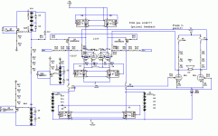
This is the original schematic.
This is my attempt at modification. Does this make a SUSY circuit? (Or would it even work, or blow up or something?)
I moved feedback from the sources to the gates, crossing it (actually the cross is at the top of the first stage), and added the 5 ohm resistor between the sources (I'm just guessing at the values here). Input resistors are for protection, since output has 800 V swing.
will work except for the fact that the input impedance
is now 1k which may be hard on a number of preamps
especially tube units and the gain is now only 200
which means you need at least 4 volts of drive voltage.
Better to make the 1k resistor 200 ohms, and plan on
having a preamp that can drive this. Also low impedance
step attenuators are hard to find.
quote
Talk about carrying coal to Newcastle ! -- somehow I miss the point of using two half-wave bridges for two regulators -- if you have a center tapped transformer you can use a full wave bridge and pull the ground return from the CT.
Not when you want to use the much more available n channel
fets for the regulated power supplys... Two seperate
regulated 400 volt supplies tied together at the output to
generate +/-400 volts. Can't do this with a center tap.
Kevin: Can't gain be increased by lowering the feedback, or would it be too low if reduced from what it currently is?
So there's no way to set up a higher input impedance in this configuration?
To the supersymmetry guys: my original question is still unanswered -- does this make a SUSY circuit or am I missing something?
So there's no way to set up a higher input impedance in this configuration?
To the supersymmetry guys: my original question is still unanswered -- does this make a SUSY circuit or am I missing something?
quote
Kevin: Can't gain be increased by lowering the feedback, or would it be too low if reduced from what it currently is?
So there's no way to set up a higher input impedance in this configuration?
Now you are actually starting to think about what you
are trying to do.
Gain is only increased in one of two ways.
For your input circuit either
1) lower the input resistor from 1k to 200 ohms, bad for all sorts
of reasons unless you really have a preamp that likes
this sort of thing (i build preamps that drive 50 ohms)
The 10k to ground resistor may in fact not be low enough
to prevent an open input failure of the fet when power
is applied.
2) increase the feedback resistor to 1 meg. Even worse.
A 1 meg resistor of a voltage rating necessary for this has
significant built in capacitance which changes the frequency
response of the amplifier in significant and audible ways.
This is a high voltage circuit. Many techniques that work
on low voltage power amps will not apply here.
Really, no kidding.
Which of course begs the question what capacitance is acceptable anyway. And if I were to find appropriately low capacitance 1M resistors, what would be proper values for the input resistors? Is it possible to set up a configuration that would still allow the use of an attenuator? The lowest from Goldpoint are 10K for the ladder type (though they have kits so one can choose resistors).
And once again, I'm still hoping one of the people here familiar with supersymmetry will help me out with my original question. Depending on the answer I may be wasting my time changing the original schematic (at least Keving seems to think so).
And once again, I'm still hoping one of the people here familiar with supersymmetry will help me out with my original question. Depending on the answer I may be wasting my time changing the original schematic (at least Keving seems to think so).
- Status
- This old topic is closed. If you want to reopen this topic, contact a moderator using the "Report Post" button.
- Home
- Amplifiers
- Headphone Systems
- SUSY for electrostatic headphone amp