This is the new discussion thread for the Sapphire amplifier.
Previous threads,
183588-headphone-amplifier-drop-replacement-phonoclone-3-vsps300
160460-rjm-audio-gainbloc-preamplifier-mk-i
are redirected here.
Information about the kit group buy is at this thread.
Previous threads,
183588-headphone-amplifier-drop-replacement-phonoclone-3-vsps300
160460-rjm-audio-gainbloc-preamplifier-mk-i
are redirected here.
Information about the kit group buy is at this thread.
Attachments
 Very good design RJM. I've tried this with very good results.
 Yep, LH0002 buffer, lifted directly from the datasheet... with one little twist:
I realized that the National circuit works as it does specifically because it is an integrated circuit. All the transistors in the same package mean they all share thermal equilibrium. Forcing everything to be at the same temperature keeps the bias current steady at the desired value. When building a discrete version it is important to have the driver and output transistors bolted together. If you don't, you have to modify the circuit to steady the bias currents electrically, which adds complication and breaks the output-driver symmetry.
I realized that the National circuit works as it does specifically because it is an integrated circuit. All the transistors in the same package mean they all share thermal equilibrium. Forcing everything to be at the same temperature keeps the bias current steady at the desired value. When building a discrete version it is important to have the driver and output transistors bolted together. If you don't, you have to modify the circuit to steady the bias currents electrically, which adds complication and breaks the output-driver symmetry.
Yes, I think I can: put 33R in series with the load. This limits the output current into a short to 300mA, 200 mA into a 16 ohm headphone load.
Or perhaps a 250 mA fuse in series with the load...
What you need depends on what you are primarily interested in protecting: the output transistors or your headphones.
Or perhaps a 250 mA fuse in series with the load...
What you need depends on what you are primarily interested in protecting: the output transistors or your headphones.
Primarily output stage if shorted to ground. Although both features would be nice to have.What you need depends on what you are primarily interested in protecting: the output transistors or your headphones.
They were cheap on eBay, easy to mount with the 4mm center hole, easy to connect with the push on lugs. And they look cool.
Thought it should have been something practical than electrical, that is why I asked. Thanks.
R14 = 33 R would do the trick. The penalty you pay is a small reduction in maximum output power, and a relatively large increase in output impedance.
Note that an shorted load will not blow the output devices unless there is a AC signal present (i.e. playing music.) The DC offset is too small to generate significant current even with the BOM value for R14 = 1 ohm.
Note that an shorted load will not blow the output devices unless there is a AC signal present (i.e. playing music.) The DC offset is too small to generate significant current even with the BOM value for R14 = 1 ohm.
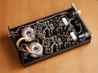
So, this afternoon I put my 14s1 Sapphire on the bench and gave it a thorough going over with the voltmeter. Before I post some photos and lose your attention for good, let me post some numbers and comments.
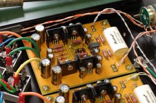
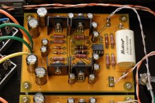
- with the rev 14 layout, putting the output and driver transistors on the same heatsink, I solved the "reverse thermal runaway" issue that, in the rev 10 prototype, caused a significant reduction in output bias. I'm getting within 10% of the worksheet values, that 10% difference is most likely because the calculation assumes the devices are at the same temperature when in reality the drivers are a little bit warmer as the thermal coupling is not 100%.
- every other test point is spot on.
- in my build I have R10,R11 = 360 R and R6 = 13k. All other values as per the BOM.
- Talema 62062 transformers, but I'm running on 100 VAC line (Japan) so the effective secondary rating is 10.7 V rather than 12 V.
(I adjusted my version of the worksheet to reflect those changes before comparing the measured and calculated values)
Unrectified DC is +/-15.7 V. Regulated voltage rails are +/-10.8 V.
Measured driver current is 28 mA [calc=measured]. Measured output bias is 19 mA [calc=measured*1.1]. With my HD600 headphones, 23 dB gain and 64 mW of class A output power (calculated).
-The only surprising thing, to me, is how hot things got. Total heat for the stereo amp is 5 W, 0.5-1 W per heatsink. Overall the whole case gets comfortably warm when left on for a while. The heatsinks with two transistors against them are just cool enough to be able rest your finger against. Probably about 55 degrees C, or 20 C degrees above ambient (it's still hot here). My conclusion is that I would not want to increase the bias currents much above what they already are without a complete rethink of the thermal design of the amp.
Final word: Sapphire rev 14 works as designed, and is pretty well optimized at the current circuit values.
Last edited:
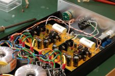
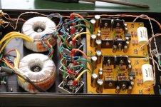
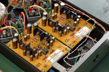
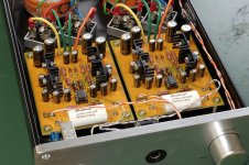
Sapphire Desktop Headphone Amplifier
(after fitting the new rev 14 boards)
- R6 is 13k tantalum, I grabbed them at hifi DIY store in Osaka.
- R10,R11 is the 360 ohm resistors from my proto built and were spliced in there after I mistakenly fitted 330k ohm resistors in there by mistake.
- The heatsinks are the wrong size, but they'll do until I get the new ones.
- The bridges, for the record, are 400V 50A each.")
[Nikon D40, Ai micro-Nikkor 55mm F3.5]
(after fitting the new rev 14 boards)
- R6 is 13k tantalum, I grabbed them at hifi DIY store in Osaka.
- R10,R11 is the 360 ohm resistors from my proto built and were spliced in there after I mistakenly fitted 330k ohm resistors in there by mistake.
- The heatsinks are the wrong size, but they'll do until I get the new ones.
- The bridges, for the record, are 400V 50A each.
[Nikon D40, Ai micro-Nikkor 55mm F3.5]
Attachments
Last edited:
Btw, where do you source those nice enclosures from?
Regards,
Venci.
Ebay is another source. I saw this there several times.
By the way RJM, the Sapphire looks good. Good job!
I was scouring the internet for headphone amplifier circuits similar to the Sapphire : a current buffer running open loop, with either a discrete or integrated voltage front end. Other than the 47 labs model 0147 I haven't found anything. Dozens of diamond buffer variants out there, all complications of the basic LH0002 caliber - I think I've seem most of them now. Several "diode biased push-pull transistor pair" output stages stapled into the op amp feedback loop. Nothing I could really point to and say "hey that's pretty much the same as the Sapphire."
I'm interested because I'd like to know how other people approached a similar design, what they did differently, and why, maybe learn some new tricks.
Anyone care to point me in the right direction?
I'm interested because I'd like to know how other people approached a similar design, what they did differently, and why, maybe learn some new tricks.
Anyone care to point me in the right direction?
True, there's that. Still available too, I though it was discontinued for some reason. Unfortunately it is fixed at about 6 mA quiescent current, so it more-or-less has to be used inside the feedback loop.
I was searching instead for example circuits where the output buffer is run open loop.
I was searching instead for example circuits where the output buffer is run open loop.
- Home
- Amplifiers
- Headphone Systems
- RJM Audio Sapphire Desktop Headphone Amplifier