I would counsel against putting the IEC jack on the board like that if the boards are to be fixed to the bottom plate of the chassis rather than the back panel. As it is now, the back cutout must be perfectly aligned or you'll have to shim the standoffs. Not fun.
I don't feel there is particular need for additional filter capacitance on the power supply board like that, but it is up to you if you want to include it.
Surface mount diodes are fine is someone else is installing them, but I think through hole would be a better choice for diy.
I don't feel there is particular need for additional filter capacitance on the power supply board like that, but it is up to you if you want to include it.
Surface mount diodes are fine is someone else is installing them, but I think through hole would be a better choice for diy.
I would counsel against putting the IEC jack on the board like that if the boards are to be fixed to the bottom plate of the chassis rather than the back panel. As it is now, the back cutout must be perfectly aligned or you'll have to shim the standoffs. Not fun.
I don't feel there is particular need for additional filter capacitance on the power supply board like that, but it is up to you if you want to include it.
Surface mount diodes are fine is someone else is installing them, but I think through hole would be a better choice for diy.
rjm, thanks for the feedback!
I luckily have access to a CNC machine I'll be using to for the rear panel cutouts, so hopefully alignment won't be an issue. Also, I just built a reflow oven, so I'm using this as a chance to give SMDs a try.
I've added the extra filter caps because this will be powering an additional circuit per channel, a relay switched passive attenuator when I get time to design it.
Thanks again for your comments, I just got my DigiKey order in with the rest of the amp components, can't wait to get it built!
I'm certainly looking forward to seeing the final result.
Thanks! I'm looking forward to finally listening to this amp after sitting on it for a few months (almost a year?!).
I spent some time last night matching the transistors on hfe. If anyone is interested, I did the matching using one of the Atmega328 transistor tester kits available on eBay and elsewhere. Initially, I was skeptical of its accuracy so I validated some tests using the circuit outlined at http://www.geofex.com/article_folders/ffselect.htm. Overall, they agreed and made testing 200 transistors much easier!
RJM, my results in the grouping of transistors were very similar to your observations in #438. The NPNs were very tightly grouped for about 80/100. The PNPs were much more widely distributed. I ended up selecting the tightest group of 18 PNPs as near to the commonly occurring hfe for the NPNs (288).
I am just about ready to sit down and start soldering, but before I proceed a quick question:
The metal film resistors I am using (Takman REY25) are not available in 1 ohm. Instead, I have 2.2 ohm resistors to use for R19, 20, and 21. How important is it for these to be 1 ohm? I must say I don't understand the circuit enough to understand their purpose or the impact of changing this value. I do have 1 ohm resistors available but it will clash with my resistor color scheme
 .
.The change to R21 won't do anything but increase the output impedance by an ohm. Changing R19 and R20 will reduce the output bias current from 32 mA to about half that.
If you are really worried about your paint job use 2x 2.2 resistors in parallel, the second one can be soldered to the underside of the board.
If you are really worried about your paint job use 2x 2.2 resistors in parallel, the second one can be soldered to the underside of the board.
If anyone is interested, I did the matching using one of the Atmega328 transistor tester kits available on eBay and elsewhere.
I have several variations of these Chinese component testers.
When checking the Hfe of transistors, I notice I can get a different reading every time I push the "test" button.
Hfe can vary as much 10 or 12 for a given transistor.
I noticed nobody else has mentioned this about these testers.
So are you supposed to take an average of several readings, or what?
When checking the Hfe of transistors, I notice I can get a different reading every time I push the "test" button.
Hfe can vary as much 10 or 12 for a given transistor.
The Atlas tester I use is much more consistent. I think it's an Atlas DCA55. I can recommend it.
The Atlas tester I use is much more consistent. I think it's an Atlas DCA55. I can recommend it.
Agree. I have noticed that parts from a single run (i.e. parts from same reel or with same date code) are more consistent than parts from different runs.
In a PM with another forum member, it was suggested that I use the tester to find the "outliers", or the grossly dissimilar parts, and exclude them from the selection. In a decent circuit the hFE and/or Vbe values should not dominate the results. I'd offer that a 10-20% variance is pretty close, but as always YMMV.
The Atlas tester I use is much more consistent. I think it's an Atlas DCA55. I can recommend it.
Thank you for the recommendation. Hopefully I can get one in the future.
There's also the DCA75, which is probably the one I'd get. The main difference is the DCA75 measures to 12 V 12 mA rather than the DCA55's 5 V 5 mA limit.
I already have a cheap DUOYI DY294 and the reason I haven't bought the DCA75 yet is that while the PC interface and curve plotting functions are fun and interesting all I really need is the transistor hfe, which the DY294 will measure just fine.
I already have a cheap DUOYI DY294 and the reason I haven't bought the DCA75 yet is that while the PC interface and curve plotting functions are fun and interesting all I really need is the transistor hfe, which the DY294 will measure just fine.
There's also the DCA75, which is probably the one I'd get. The main difference is the DCA75 measures to 12 V 12 mA rather than the DCA55's 5 V 5 mA limit...
If I was buying one today, that's what I'd buy. When I purchased my DCA55, the 75 was not yet available. Even so, the DCA55 has been a very useful tool and I'd say that if you can get a good price on a used one, grab it.
The Atlas does look nice, maybe if I'm itching to add to the tool collection in the future. The Atmega based tester seems good enough to get the components binned or at least filter out the outliers.
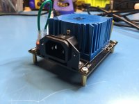
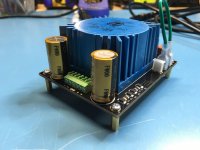
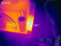
Meanwhile, my PSU PCBs arrived and the initial build looks promising! I ran it for a while with a 1A load @ 15V and nothing melted on me!
Meanwhile, my PSU PCBs arrived and the initial build looks promising! I ran it for a while with a 1A load @ 15V and nothing melted on me!
Attachments
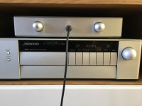
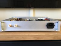
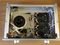
Just wanted to thank Richard for a great kit and fantastic email support (I had soldered Q2 on one of the boards back to front - doh!). I haven't done a great deal of listening yet, but first impressions are very good, nice dynamic sound, plenty of depth and space through my Grado SR80's.
The case is from ebay: Aluminum Chassis Amplifier Enclosure Preamp Case Headphone Cabinet DAC box | eBay
Nick
The case is from ebay: Aluminum Chassis Amplifier Enclosure Preamp Case Headphone Cabinet DAC box | eBay
Nick
Attachments
I was bought Tube buffer/preamp and connect before Sapphire. Schema of very similar is here: http://www.diyaudio.com/forums/tubes-valves/286349-6j1-tube-buffer-circuit-diagram.html
Is write buffer, but it is preamp - on full have about 6x voltage gain. I set Sapphire opamp to unity gain and use gain of tube. Result is very good.
I have one idea - Can I drive directly Sapphire diamond buffer with tube? My idea is remove opamp and connect tube circuit instead (use 2520 pins V+, GND and OUT for comfortable connection).
The op amp provides voltage gain and a low impedance drive for the buffer input (the output buffer is made up of bipolars and isn't too happy driven by a high impedance source).
You should be able to substitute it with a tube stage. You will typically have a coupling cap now between the tube output and the buffer input, so you'll need a resistor from the buffer input to COM to provide a DC drain for the base currents. It needs to be relatively small, 10k or less, so your tube stage needs to have the appropriate drive.
You should be able to substitute it with a tube stage. You will typically have a coupling cap now between the tube output and the buffer input, so you'll need a resistor from the buffer input to COM to provide a DC drain for the base currents. It needs to be relatively small, 10k or less, so your tube stage needs to have the appropriate drive.
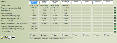
Today I replaced the power transformers on my Sapphire 31n with Triad VPM 24-1040 medical grade toroids.
These are 25 VA models, and note they were a very tight squeeze into my existing case. If I was doing it again, I would plan on not going dual mono on the power supply.
The reason for the upgrade is 1) the electrostatic screen and built in magnetic shield, which the regular Triad models don't have, and 2) the dedicated 100 VAC taps on the primary for Japan line voltage.
I got them at Mouser, but Digikey also stocks them.
I don't feel they made a huge difference, honestly, compared to my permalloy wrapped standard Triad models, but according to RMAA I've gained a dB here, a dB there.
Considering the cost of buying your own permalloy sheets, the VPM are something of a bargain and I'd definitely recommend them.
Attachments
Last edited:
I make Sapphire 31n amplifier, and I have a few questions.
Two transformers 15W (2х12V, 0.55A) will be enough?
Can I use a single transformer 40W (2x12V, 1.5A) and rectifier circuit in the picture?
I have DC voltage (0.015V and 0.01V) at amplifier output. It is within the norm?
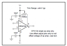
OPA134PA has Offset Trim. This adjustment will work?
Two transformers 15W (2х12V, 0.55A) will be enough?
Can I use a single transformer 40W (2x12V, 1.5A) and rectifier circuit in the picture?
I have DC voltage (0.015V and 0.01V) at amplifier output. It is within the norm?
OPA134PA has Offset Trim. This adjustment will work?
Attachments
- Home
- Amplifiers
- Headphone Systems
- RJM Audio Sapphire Desktop Headphone Amplifier