So. And therein lies the problem of using headphone amplifiers in general: they can do nothing but harm when connected to a noisy output.
In your case you'd be better off I think using an analog volume control between the RPi and Sapphire. That would improve your S/N vs. using digital attenuation at the source, since the noise originates at the source output and not the Sapphire input stage.
In your case you'd be better off I think using an analog volume control between the RPi and Sapphire. That would improve your S/N vs. using digital attenuation at the source, since the noise originates at the source output and not the Sapphire input stage.
i was looking along those lines. think i'll start looking for another DAC board without a built in headphone amp or see if i can bypass the one on this board.
one more thing i have done tonight was disconnect the PE and it could be placebo but it does sound cleaner to me, even son #2 noticed the difference listening to Florence in the machine.
its all fun and keeping me amused")
one more thing i have done tonight was disconnect the PE and it could be placebo but it does sound cleaner to me, even son #2 noticed the difference listening to Florence in the machine.
its all fun and keeping me amused
To be honest it's driving me a bit batty. The noise spectrum varies slightly and the intensity shifts between channels if I move the cable connecting the Sapphire output to the sound card input.
That said though all my messing about over the last 2 weeks seems to gave netted me a genuine 4-6 dB lower noise.
I need a better cable. It's 6.3mm - 6.3mm stereo phone plug, an oddity for hifi and I don't have anything on hand other than a cheap 3.5mm mini cable and two 3.5-6.3 adapters.
That said though all my messing about over the last 2 weeks seems to gave netted me a genuine 4-6 dB lower noise.
I need a better cable. It's 6.3mm - 6.3mm stereo phone plug, an oddity for hifi and I don't have anything on hand other than a cheap 3.5mm mini cable and two 3.5-6.3 adapters.
i dont know what i have done but i'm liking the results. the bass on my dt880's with dt770 ear pads was always like canons going off in my ears at the expense of mid and top end clarity, well for some reason the mid and top have now come alive and upto the same level and i have gained the clarity of the dt880 pads but with the thunderous bass of the dt770 pads.. yeeehawwww.
In your case you'd be better off I think using an analog volume control between the RPi and Sapphire.
nope its even worse. 50hz now increases with stepped attenuator volume.
Yes, of course it will. It will not be as loud as without the volume control, however, unless the volume control is at 100%. That's what the attenuator does after all: attenuate the input signal.
The attenuator will not change the signal-to-noise until the signal is so low that the input noise of the amplifier becomes important. You can increase the signal-to-noise by turning the digital attenuation to 100%, and not lose any of that from turning down the analog volume, until the limit of the amplifier input noise is reached.
Let's run through the numbers, imagining your Sapphire gain is 26 dB and your desired output level is 0 dB.
Your RPi output noise is -91 dB, right? Your digital attenuation is -26 dB and the Sapphire gain is 26 dB to obtain the output of 0 dB signal. Digital attenuation will not reduce the noise floor, so the output noise is -65 dB and S/N a poor 65 dB.
If you leave the digital attenuation at 100% (0 dB) and dial -26 dB with an analog volume, followed by 26 dB from the Sapphire, the -91 dB noise is first reduced by 26 dB then increased by 26 dB leaving you with -91 dB or 91 dB S/N. Since the Sapphire output noise is at worst ~-100 dB it's contribution has no impact on total S/N.
I should add that in my own case the noise is induced in the Sapphire boards themselves or the output cable. Digital, analog attenuation... it's all one and the same. Even if that wasn't the case, it would be a tossup I think as to which would be preferred. Switching to baseline noise figures for a moment, 8 nV of the OPA134 in the Sapphire gives -162 dB input referred while the output noise of the DAC/NE5532 in the sound card probably around the same (A-weighting is hard to decipher.) Which as far as I can work out means its a "six of one / half dozen of the other" scenario.
Last edited:
Things are much improved.
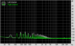
First plot is the baseline noise, vol -inf. no input.
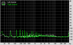
Second is at 0 dB net gain, input connected, default RMAA measurement setting.
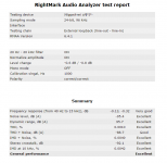
RMAA results posted for reference. Channel imbalance is the input section of the soundcard, nothing to do with the Sapphire3. All measurements were performed with the amp unloaded. ASUS Xonar STX soundcard.
The chassis is connected at the headphone jack, and the transformers shielded. (other changes, new Oyaide cable to connect amp and soundcard input, and fixed a possibly cracked lead on the left channel at the output.)
Despite the peaks in the FFT, the amp is 'is this thing on' silent for all intents and purposes.
First plot is the baseline noise, vol -inf. no input.
Second is at 0 dB net gain, input connected, default RMAA measurement setting.
RMAA results posted for reference. Channel imbalance is the input section of the soundcard, nothing to do with the Sapphire3. All measurements were performed with the amp unloaded. ASUS Xonar STX soundcard.
The chassis is connected at the headphone jack, and the transformers shielded. (other changes, new Oyaide cable to connect amp and soundcard input, and fixed a possibly cracked lead on the left channel at the output.)
Despite the peaks in the FFT, the amp is 'is this thing on' silent for all intents and purposes.
Attachments
Last edited:
that looks superb Richard.
been messing with mine as well 50hz is now around -80db@50hz (with RPi connected).
removed the input resistor and bridged, removed feedback resistors to 1k and 10k (still plenty loud enough) and added a 2.2uf cap (could do with being bigger) to the + output which gives me 0dc at the headphone socket, reduces the bass slightly but cleans the top end up and vocals are much smoother. all in all about the same but cleaner sounding.
Wish I could say what exactly it was, but something just "clicked". Not just the noise floor, definition & dynamics too have improved.
(I was using the K702 for a while, then went back to the HD600, and after using the Mundorf SupremeEX switched back to the Multicap PPFXS. The Rike are unfortunately too big to work comfortably in my case ... they get too close to the output wires, causing interference.)
(I was using the K702 for a while, then went back to the HD600, and after using the Mundorf SupremeEX switched back to the Multicap PPFXS. The Rike are unfortunately too big to work comfortably in my case ... they get too close to the output wires, causing interference.)
There are two types of interference that you need to deal with:
Shielding and grounding all work well for RFI, but I have run into problems with EMI at the power frequency from the transformer. Low frequency radiation from the power transformer can induce currents into the amplifier's wiring and components (e.g. large capacitors). The usual RFI screening is ineffective against the strong low-frequency electro-magnetic field. I had a similar problem where a headphone amplifier I built had a low-level background buzzing, which appeared as small voltage spikes in sync with the AC mains, but not exactly the diode switching. These were clearly visible on the oscilloscope at a few millivolts. I spent much time perfecting grounding and RF shielding to no significant benefit. I wondered how to deal with EMI.
Researching EMI shielding brought up two options:
I tell you this story to help with a little bit of lateral thinking - i.e. questioning what is it that you are shielding the signal from?
Google turns up a lot of results when you know what to search for: electromagnetic lossy shielding eddy current.
Here's a link to another thread here (I'm, not sure of my original source): http://www.diyaudio.com/forums/tubes-valves/154198-magnetic-shielding-aluminum.html
- RFI - radio frequency interference
- EMI - electro-magnetic interference
Shielding and grounding all work well for RFI, but I have run into problems with EMI at the power frequency from the transformer. Low frequency radiation from the power transformer can induce currents into the amplifier's wiring and components (e.g. large capacitors). The usual RFI screening is ineffective against the strong low-frequency electro-magnetic field. I had a similar problem where a headphone amplifier I built had a low-level background buzzing, which appeared as small voltage spikes in sync with the AC mains, but not exactly the diode switching. These were clearly visible on the oscilloscope at a few millivolts. I spent much time perfecting grounding and RF shielding to no significant benefit. I wondered how to deal with EMI.
Researching EMI shielding brought up two options:
- distance - move the transformer physically further away.
- special metal, such as mu-metal.
I tell you this story to help with a little bit of lateral thinking - i.e. questioning what is it that you are shielding the signal from?
Google turns up a lot of results when you know what to search for: electromagnetic lossy shielding eddy current.
Here's a link to another thread here (I'm, not sure of my original source): http://www.diyaudio.com/forums/tubes-valves/154198-magnetic-shielding-aluminum.html
Q. if i took some two core microphone cable and used the two cores for hot/cold then connected the screen to GND on the boards would that screen the cable from interference?
Electro-magnetic fields from the transformer will not be effectively shielded by normal screened cable. I was able to suppress an annoying low level background buzz being picked up from my transformer by installing a 12mm thick aluminium barrier between the toroidal transformer and my circuit (large metal file input caps). The buzz showed up on the oscilloscope as little spikes of a few millivolts and were audible when no music was playing.
Here's a thread that might help: http://www.diyaudio.com/forums/tubes-valves/154198-magnetic-shielding-aluminum.html
I'd actually read a very similar thread on another audio forum. The gist is the same: a reasonable thickness of metal between circuit and transformer will reduce EMI especially at higher frequencies. My copper cummerbunds around the transformers were based on this notion, that non-ferrous metals are better than nothing.
I'm not sure if I'm up to building aluminum plate bulkheads in my already crowded chassis, but I'm definitely keeping this advice in mind for my next build.
I'm not sure if I'm up to building aluminum plate bulkheads in my already crowded chassis, but I'm definitely keeping this advice in mind for my next build.
Sorry for the double post, I thought the first one had got lost. I didn't realise I was subject to moderation at this stage. I hope it didn't seem like I was labouring my point. I could see @Bibio following a similar path to mine, so thought I add an idea from my experience. @rjm, I've been following your design because it is similar to some ideas I have had, but your implementation seems very thorough. I would like to build it, but unfortunately I have a few too many projects on the go to start this right now, but I will go back to "interested lurker" until further notice.
6 years and you are finally off moderation. Congrats!
I was just going to add that the description of your noise: "appeared as small voltage spikes in sync with the AC mains, but not exactly the diode switching" sounds very like what I have, rather than the what Bibio was getting on his which is closer to hum/ripple.
Like you, I also arrived at the conclusion that the biggest receiver for the transformer-generated EMI is in fact the input coupling caps. Those big, highly inductive audio film caps suck up the magnetic energy and dump it straight into the op amp inputs.
- Home
- Amplifiers
- Headphone Systems
- RJM Audio Sapphire Desktop Headphone Amplifier