notes in testing-
As before, the loopback condition used for testing with, e.g. Rightmark, injects noise that it not present during normal operation. Measurements obtained this way are worse than useless. That said, the effect is worse than the previous version - I expect it is caused by taking the chassis connection from GND instead of OUT-, will verify.
I have reduced R9,10 fom 5 ohms to 1 ohm, bias current falling from 70 mA to just 16 mA. Initial impression is it doesn't change much. Sound is very slightly lighter, rougher, and less well defined.
I like being in the position to make just one change and compare the sound. Its only there that one can really start to make conclusions about what does what.
In this case I'm looking at 16 mA vs. 70 mA bias current. Extended listening reveals some interesting things:
Two posts up I said "lighter" and I stand by that: it's like an invisible hand had backed off, leaving the music more room to breathe. Literally more air. Better musical phrasing, easier to pick out the vocals, rhythmically more tuneful. For that, there is a loss of control and sheer physical heft, particularly of the bass frequencies.
With my 300 ohms headphones, I have to say that overall I prefer the sound with bias current dialed back, though perhaps not as much as I have now.
20-30 mA seems like a nice range to aim for, so R9,10 from 2.2 to 3.3 ohms.
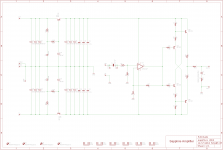
(schematic is two posts up)
The way the values work themselves out is as follows:
Chose the bias current. Practical values range from 20 to 120 mA. Anything above 20 mA will ensure the amp runs in class A for 99.9% of all headphones and usage cases.
The emitter resistors R11 and R12 are equal to 26/(bias current in mA). Thanks to AndrewT for letting me know that little fact.
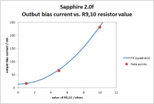
Then, the bias resistors R9 and R10 have to chosen to get the desired bias current. There is no quick and easy formula for that, so I will list a few setpoint examples. These are calculated, and may be off by as much as 20%, so just as a guide only:
Bias current ------ R9,10 --------- R11,12
30 0.84 4.6
50 0.69 6.0
80 0.33 7.4
100 0.25 8.2
120 0.22 8.7
If R11,12 is slightly higher than listed, increasing R9,10 slightly will compensate.
Now, what is the best sounding bias current? We're working on that...
The way the values work themselves out is as follows:
Chose the bias current. Practical values range from 20 to 120 mA. Anything above 20 mA will ensure the amp runs in class A for 99.9% of all headphones and usage cases.
The emitter resistors R11 and R12 are equal to 26/(bias current in mA). Thanks to AndrewT for letting me know that little fact.
Then, the bias resistors R9 and R10 have to chosen to get the desired bias current. There is no quick and easy formula for that, so I will list a few setpoint examples. These are calculated, and may be off by as much as 20%, so just as a guide only:
Bias current ------ R9,10 --------- R11,12
30 0.84 4.6
50 0.69 6.0
80 0.33 7.4
100 0.25 8.2
120 0.22 8.7
If R11,12 is slightly higher than listed, increasing R9,10 slightly will compensate.
Now, what is the best sounding bias current? We're working on that...
How does the bias current in the output effect the op-amp? Is it running in class A - I do not see this mentioned by the Burr Brown specification sheet. No matter what bias you run through the output, the cross-over distortion is present as for any class B amplifier. The fact that this is an instrumentation amp does not necessarily make it suitable for anything else.
I think setting the bias current in the output and hearing a difference is placebo effect more that anything else.
I think setting the bias current in the output and hearing a difference is placebo effect more that anything else.
Hello, RJM.
I still haven't tested the Sapphire since I left the audio stuff behind for a while with other priorities consuming most of my time. Yet, during the holidays I decided to see what is on the shortlist and this was the first project to look at. Checking if I made my schematics properly, I noticed that you have updated the Sapphire. Once again - your work is very impressive and I truly admire it.
Regarding some of the changes made, allow me to share some of my concerns:
* My personal view is that OPA2134 is not the best suited as high voltage gain input stage. It is JFET, which is noisier than some fine BJT examples. I would personally start with something more like AD8597, LME49710 etc as long as DC-offset is kept in mind.
* At high gains, a high-performance, uncompensated parts could also be used, i.e. NE5534 and ADA4637-1BRZ for a better low-frequency response. Perhaps a cap could be provisioned in the opamp's feedback loop for a high-frequency stability.
* Mixture of 0.1uF ceramics and 100uF electrolytics is resulting in 1:1000 ratio and may, in some cases, cause a possible resonace issue at high frequencies (resulting in higher impedance of the power supply), which will be more evident for high-performance parts with stability issues combined with ultra low ESR electrolytic capacitors (something Nichicon FW are not known for). The V-Reg does a great job isolating the big cap tanks. You may want to check AD797 datasheet, "bypassing considerations" for more detailed view on that.
* Again a personal view of mine for analog audio circuits I consider the power supply to be part of the signal path and for high-performance designs I would rather choose a PP bypass over PE or X7R. Same is also valid for the Zobel network and having in mind that SMD parts have nickel plated terminals, this will probably diminish its performance versus a good, low-inductance cap. This is more like nut-picking I believe.
Best Regards,
GLooP
Last edited:
Today I got to go back and experiment a little.
I removed the j-mo from the same chassis as the sapphire to allow me a little more room to work. Annoyingly, I had earmarked a couple of 12V tx for this build, but when I had them in hand I realised they were a single secondary only. Grr.
So I added in a new gigawork type pot with very short signal wiring - the pot is mounted at the back of the chassis right at the input RCAs. There is quite a bit of improvment with these pots over the alps blue that had been serving in that role. At ~$12 each thye are great value.
Next easiest thing to do is to experiment a little with the input cap - I swapped in a 2.2uF Russian K75-16 cap. To my ears there is greater detail - not massive, but cleaner I think.
Richard, perhaps you would send on the mods to go from my 1.4 to v2?
Also - the zobel - I can't find a low value cap in my stash, is the 4n7 value critical?
Fran
Attachments
Last edited:
@Nico Ras : The op amp I'm using presently is the OPA134. It's an audio op amp, low distortion, FET input. I'm sure its output bias current is already optimized.
@GLoop : thanks indeed for sharing your thoughts. Let me break down my comments individually,
1. It's not a high voltage gain application. Quite the opposite. We are looking at low gains (<20 dB) and low bandwidth, so we want low noise, low distortion, and stable operation. I would not choose to use a de-compensated op amp here. Since it backs a 50k volume potentiometer, low current noise is desirable suggesting FET-input type. I've tried both JFET and BJT, and to be honest there isn't a lot of difference. I happen to like the OPA134. I've limited my evaluation to DIP8 packages however.
2. People tend to divide out into camps over this one, but I'm firmly convinced that ceramic capacitors are the absolute best option for bypassing duty. For audio frequency filters, networks, and coupling applications its a different story, but for bypassing electrolytics the very last thing you want to use is a high-inductance metallized film, or metal foil capacitor. For the exact reason to avoid the LC tank resonance you mention. Whether that makes anything audible I can't say, but I did listen to the Sapphire with/without the ceramic caps installed and, well, there's basically no difference. If I could convince myself of anything, it was that they add tiny bit of smoothness, like some RFI hash has been quenched. That's it.
@Hi Fran!
Ok, I'll try and sketch up a hack to add the adjustable bias function to your 1.4 boards. I'm still working on optimizing the circuit values on v2, specifically the output bias current and related resistances. That's on the books for later today. My strategy here is pretty crude: the first built at 70 mA was too "heavy" sounding, the second build at 16 mA was too "light". Previously with the 1.4 boards I also tried 8 mA (way too light, harsh) and about 20 mA (pretty good), so doing some obvious interpolation I conclude that 25-30 mA should be just right. I call it the "goldilocks stratagem"") .
.
@GLoop : thanks indeed for sharing your thoughts. Let me break down my comments individually,
1. It's not a high voltage gain application. Quite the opposite. We are looking at low gains (<20 dB) and low bandwidth, so we want low noise, low distortion, and stable operation. I would not choose to use a de-compensated op amp here. Since it backs a 50k volume potentiometer, low current noise is desirable suggesting FET-input type. I've tried both JFET and BJT, and to be honest there isn't a lot of difference. I happen to like the OPA134. I've limited my evaluation to DIP8 packages however.
2. People tend to divide out into camps over this one, but I'm firmly convinced that ceramic capacitors are the absolute best option for bypassing duty. For audio frequency filters, networks, and coupling applications its a different story, but for bypassing electrolytics the very last thing you want to use is a high-inductance metallized film, or metal foil capacitor. For the exact reason to avoid the LC tank resonance you mention. Whether that makes anything audible I can't say, but I did listen to the Sapphire with/without the ceramic caps installed and, well, there's basically no difference. If I could convince myself of anything, it was that they add tiny bit of smoothness, like some RFI hash has been quenched. That's it.
@Hi Fran!
Ok, I'll try and sketch up a hack to add the adjustable bias function to your 1.4 boards. I'm still working on optimizing the circuit values on v2, specifically the output bias current and related resistances. That's on the books for later today. My strategy here is pretty crude: the first built at 70 mA was too "heavy" sounding, the second build at 16 mA was too "light". Previously with the 1.4 boards I also tried 8 mA (way too light, harsh) and about 20 mA (pretty good), so doing some obvious interpolation I conclude that 25-30 mA should be just right. I call it the "goldilocks stratagem"
.Thanks, but I've played that game already! Settled on the Multicap PPPMSNX-something-or-other (the tin foil, expensive ones...).
I forgot to answer your question about the Zobel: any reasonable combination of R and C that give an RC time constant of about 0.2 microseconds will be acceptable. 5n and 47ohms, 10n and 22 ohms, 22n and 10 ohms etc, but keep R from 10 to 100 ohms.
I forgot to answer your question about the Zobel: any reasonable combination of R and C that give an RC time constant of about 0.2 microseconds will be acceptable. 5n and 47ohms, 10n and 22 ohms, 22n and 10 ohms etc, but keep R from 10 to 100 ohms.
"I love it when a plan comes together" - George "Hannibal" Smith
The "Goldilocks stratagem", and my interpolation numbers, paid off.
R9,10 = 4.7 ohms, R11 12 = 1 ohm gives a bias current of 28.5 mA and a sound that gets the balance of power and agility just right, and the additional advantage of a moderate power draw and heat signature, <4 W idle for the stereo circuit.
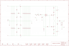
The schematic and BOM have been updated accordingly, with the additional change making R15,16 = 1k, reducing the Zener current a little to match the lower bias currents.
(Internally I give circuit revisions that do not change the board layout a number suffix, so 20f, 20f2, 20f3 etc. This is "f4" and I've uploaded to the new files to the web page also.)
The "Goldilocks stratagem", and my interpolation numbers, paid off.
R9,10 = 4.7 ohms, R11 12 = 1 ohm gives a bias current of 28.5 mA and a sound that gets the balance of power and agility just right, and the additional advantage of a moderate power draw and heat signature, <4 W idle for the stereo circuit.
The schematic and BOM have been updated accordingly, with the additional change making R15,16 = 1k, reducing the Zener current a little to match the lower bias currents.
(Internally I give circuit revisions that do not change the board layout a number suffix, so 20f, 20f2, 20f3 etc. This is "f4" and I've uploaded to the new files to the web page also.)
Attachments
Last edited:
Dear rjm,
Thank you for your reply. If you allow me, I would like to ask some more questions:
* Is there any specific reason behind R2, R3, R4 and using a 50k pot since the amp is not battery operated and just a tad more power would not probably hurt vs lower noise. According to the values listed here, the gain of the opamp is set to 5.7x and this is not very low. I believe lowering a bit R2, R3, R4 would give slightly lower noise and even more so when a lower R pot is used.
* I have seen some implementations where the signal is ground referenced once before the input cap and once after it with additional low-valued cap to ground in the latter case to facilitate high-frequency return to ground and provide better stability for the op-amp. What do you think about it?
* I see you have strictly went for local feedback - does this mean that global feedback is not worth sonically or this is because routing or stability issues? Doesn't global feedback actually reduce the output impedance and do you consider it again as an option after R11 and R12 are 1-ohm back again?
Thanks in advance and
Best Regards,
GLooP
Hi GLoop,
* The impedance of the volume potentiometer controls the input impedance, and, essentially, the noise in case where the op amp current noise dominates. If using BJT op amp, a slightly smaller value might be recommended - and resistors R1-4 to match, but then the amp becomes harder to drive. I've done the noise analysis. For circuit values shown the circuit input impedance (to the op amp, which controls current noise) is about 1 kohms on both inverting and non-inverting terminals (AC balanced, please note! [yeah, I'm awesome...]), just low enough the current noise to slip under the voltage noise of the typical audio opamps used. At these values, the Johnson noise of the resistors themselves is not a significant factor. The zener voltage regulation and high PSRR of the op amps themselves should insure the circuit operates at close to the noise levels dictated by these calculations, and not power line noise.(**)
* The signal in an op amp is not referenced internally to the input ground, but to one of the power pins. So, the important concern is the return of load currents to the power pins of the op amp package. The best way to insure stability is the correct implementation of power supply bypass capacitors.
* Yes, on the new boards the global feedback connection option is gone. Even when it worked (which was rare, apparently) no one liked the sound with the buffer in the feedback loop. My opinion is that a unity gain, class A buffer does not need any global feedback... indeed putting it in the loop only exposes the (high open loop gain) op amp to the potentially negative effects of the load capacitance and inductance. In the Sapphire circuit now the buffer isolates the op amp from the load, and provides low distortion, high current headphone drive.
(**) spend enough time with this and you realize that audio op amps are remarkably optimized circuits when it comes to current and voltage noise. It falls out that the natural, normal resistance values you would tend to use (starting with a volume potentiometer of 10-100 kohms) are the largest ones you can use without adding significant additional noise to the circuit... and likewise the base noise of the op amp itself is such that there is little advantage to using smaller resistors, either. Whether you sweat the details or just use typical values, the results are nicely optimized. Thank you Nat Semi, Burr Brown, Linear &co!
Last edited:
Which probably means it was often oscillating even when it did seem to "work".* Yes, on the new boards the global feedback connection option is gone. Even when it worked (which was rare, apparently) no one liked the sound with the buffer in the feedback loop.
Looking at things now, I can't say I'm terribly surprised. Especially with run of the mill (ST/Fairchild) BD139/140s, the buffer probably isn't too fast. (As a rule of thumb, it needs to be a factor of 3 faster than the opamp stage at the very least.) These aren't totally ideal for the first stage, the likes of BC546/556 or *N2222/*N2907 (or 2SC1815/2SA970 etc.) ought to be faster there even at reduced current. (And the second stage should run reasonably warm, maybe 50-75 mA.) Give the opamp a compensation cap (10-47p?) for some pole splitting action, add an RC zobel on the output, and maybe a film cap in parallel to the 4R7 if needed, and you should be getting somewhere. Simulators tend to be very handy when messing with this sort of stuff.
All that said, when using global feedback I could never get a simulated circuit with a discrete diamond buffer to give the same performance as one with a single-stage buffer when expecting the same kind of stability from both. More poles, more trouble, I guess. I assume that's why the classic Lehmann amps don't use global feedback either, though their more upscale models apparently do. (And note how they employ small-fry transistors for the first buffer stage.)
True enough, you can probably get away with an open-loop diamond buffer in many cases, but I feel it's just too much wasted performance, especially into lower-impedance loads.
Today I did the final few cleaning up bits with my sapphire build. I added the zobel at the output (10nf/20R) and also earthed each board to chassis right at the in- as mentioned before by RJM. I'm not sure which of these made a difference (the cost of doing both at once) but the sound is definitely a little more smooth with both high and low impedance cans.
Listening to some Gerry Mulligan/Paul Desmond "blues in time" as I type and the other thing I notice is how dynamic it sounds. Maybe it because its been on most of the evening and its well warmed up, but its the first time that really caught my attention.
I know this is all wishy washy with no measurements etc to back it up, but I am confident of a definite improvement.
Fran
I've spent a couple of days doing some serious listening. It's easy work: There is no listener fatigue. This is the current version, OPA134 and 28 mA of bias current. R4=10k, and that's a bit low: I'm listening at 11 o'clock typically (true 2 Vmrs input signal), so R4=15k or even 20k would be ideal with the HD600s.
Here's my observation re. bias current, based on trying 8, 16, 20, 28 and 65 mA:
There is a gradual shift with increasing bias current in favor of the bass frequencies. There is also a related and concomitant shift of the stereo image from the center towards both ears. So, at low bias currents the sound is lightweight but also compressed in space. At high bias currents the air is gone, and the stereo image has the classic headphone "blobs-in-the-ears" effect, with a suckout region in the center.
Now here's where it gets interesting: at the optimum setting that more-or-less balances the stereo image evenly between centered and L-R extremes the soundstage snaps into place ... not simply L-R but out away from you. The sound doesn't seem to be in your head any more, but moves out in front. This makes the whole listening experience far more natural. I suppose this was what the filters used in the old Headroom amps was supposed to do (but for my money never really delivered): remove the feeling of wearing headphones.
I have no idea why the sound should change like this, as the bias currents are all well in excess of the minimum needed to run the output stage in class A. However I have tried enough comparisons of different currents to be quite confident in the correlations I'm hearing.
- Home
- Amplifiers
- Headphone Systems
- RJM Audio Sapphire Desktop Headphone Amplifier