The ones marked as swage are designed to be expanded a bit mechanically to lock them in place, kind of like rivets. That doesn't mean you can't just solder them in place, though I would avoid the press fit ones. There are plenty that are specifically marked as solder in, so it shouldn't be an issue finding some.
Current Sources
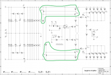
Constant current sources (current sources for short) are little circuit blocks where one or more active devices (transistors, here) replace and duplicate the function a simple resistor in a circuit.
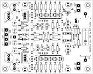
I replaced the 1k emitter resisters in the Sapphire 1~2 with the two transistor current sources highlighted in green.
The circuit is no. 4 in the following primer, which I recommend reading:
4QD-TEC: Current sources and mirrors
I posted this because I was asked about it, and I realized that it wasn't obvious what I was talking about earlier re. current sources unless you already knew what they were.
/R
Constant current sources (current sources for short) are little circuit blocks where one or more active devices (transistors, here) replace and duplicate the function a simple resistor in a circuit.
I replaced the 1k emitter resisters in the Sapphire 1~2 with the two transistor current sources highlighted in green.
The circuit is no. 4 in the following primer, which I recommend reading:
4QD-TEC: Current sources and mirrors
I posted this because I was asked about it, and I realized that it wasn't obvious what I was talking about earlier re. current sources unless you already knew what they were.
/R
Attachments
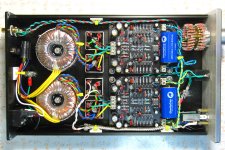
My Sapphire 3 up and running
Using my burned in .33uF Multicap input caps, I now have about three hours listening since putting the new boards in. Even before the electrolytics are burned in, there is, indeed, a new level of clarity and detail that easily surpasses 2. I'm using an Audioengine D1 as a DAC. However, I can also plug into its headphone amp, and that's provided a useful if not quite direct A-B-C comparison. For the money, I have to say that the D1 is quite good; comparing Sapphire 2 to the D1's headphone amp, I found it was sometimes a stretch to discern which was preferable. Between D1 and S2 I'd need more time with each to get past a blind test, but I'm finding that Sapphire 3 leaves no doubt. Background passages that were dense sonic textures are revealed in the details of their voices, instruments, reverb. I'm enjoying burrowing into my music library to see what things really sound like. Hard to believe, but I know that as the caps settle down things will get better.
My phones are Beyerdynamic DT880 Pro, 250 ohm.
Swapped in ClarityCaps
After 24 hrs run time, I swapped in these ClarityCaps. If first impressions are worth anything, right out of the chute, I'd say they sound a bit more open, airy, convey a sense of recording space a bit better than the Multicaps. A bit more bass extension, but no less balanced. I'm liking these a lot, will see how they break in.
After 24 hrs run time, I swapped in these ClarityCaps. If first impressions are worth anything, right out of the chute, I'd say they sound a bit more open, airy, convey a sense of recording space a bit better than the Multicaps. A bit more bass extension, but no less balanced. I'm liking these a lot, will see how they break in.
Attachments
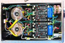
Hey Stan, what's up with your earth connections? You have bolts to the case at both the back and the front of the chassis... normally the back one connects to the IEC receptacle earth lug (AC safety earth), while the front one connects to the GND pads on both boards. And that's it. You seem to have about 3 extra ground connections happening for reasons I cannot decipher.
Hey Stan, what's up with your earth connections? You have bolts to the case at both the back and the front of the chassis... normally the back one connects to the IEC receptacle earth lug (AC safety earth), while the front one connects to the GND pads on both boards. And that's it. You seem to have about 3 extra ground connections happening for reasons I cannot decipher.
I moved the ground wires for the new boards to the rear ground post, which is where the IEC outlet is also grounded. I purposely installed two ground posts and made certain they were connected to the chassis base metal beneath the anodization. I wanted short ground connections. The Sapphire 2 boards were grounded to the front post, but the posts are "in communication" through the chassis so does it matter which ground I use? I think not but if there's a reason why not to do so, well, tell me, please.
You have the board GND connected to the rear post, but the OUT- connected from the headphone jack to the front post. Those are electrically the same thing, they are already connected internally on the boards, so you are creating a potential ground loop there.
You want GND to go to the front post to minimize wire length, while OUT- does not connect to the chassis directly.
The braid wire can connect to the chassis, to wherever is convenient.
You want GND to go to the front post to minimize wire length, while OUT- does not connect to the chassis directly.
The braid wire can connect to the chassis, to wherever is convenient.
Sapphire 30f3 point update
I still haven't got around to updating the web page from 2.0 to 3.0.
Meanwhile, though, I have done a thorough polish of the BOM, and together with the VSPS and Phonoclone, chiefly to change the resistors from Vishay CMF to KOA Speer and to use standard values where at all possible.
The following changes to the Sapphire3 were made going from the f2 to the f3 point update
* specify 20k volume control - helps keeps the noise in check.
* R2 reduced to 47k5. (100k recommended if you use 50k or 100k volume)
* R9,10 reduced from 12R to 10R ... this is done just to make the part easier to source. 12R is not "wrong".
* some other values on the schematic changed trivially (4.7 to 4.75) for consistency with the BOM.
* BOM resistors changed to KOA Speer
* the gain calculator has been expanded and re-written for clarity
The only change of real interest is the recommended volume pot. value. It's really just a guide but I think in general in 2015 we can have headphone amps with 10k or 20k input impedance as standard without inconveniencing anyone.
Attachments
Standard RJM Audio Resistor Values
1, 4.75, 10, 47.5, 100, 150, 221, 475, 1000, 1500, 2210, 4750, 10000, 22100, 47500, and 100000. Also 47 ohm carbon comp.
Non-standard values are only used when absolutely needed, like in the RIAA values in the Phonoclone or the to get the proper output voltage in the X-reg.
1, 4.75, 10, 47.5, 100, 150, 221, 475, 1000, 1500, 2210, 4750, 10000, 22100, 47500, and 100000. Also 47 ohm carbon comp.
Non-standard values are only used when absolutely needed, like in the RIAA values in the Phonoclone or the to get the proper output voltage in the X-reg.
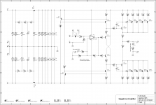
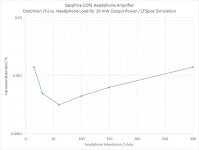
LT Spice simulation, with the latest BOM (R9,10 = 10 ohms, 33 mA total output bias current).
10 mW is a good estimate for the absolute upper limit for the output power you might ever use in listening to music with headphones. I would be very unlikely I'd exceed 1 mW even momentarily.
Distortion can therefore be capped at <0.002%, 16-300 ohms.
10 mW is a good estimate for the absolute upper limit for the output power you might ever use in listening to music with headphones. I would be very unlikely I'd exceed 1 mW even momentarily.
Distortion can therefore be capped at <0.002%, 16-300 ohms.
Attachments
- Home
- Amplifiers
- Headphone Systems
- RJM Audio Sapphire Desktop Headphone Amplifier