hello everybody,
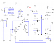
I'm going to test this simple amplifier for my 32 ohm sennheiser hd 448, the voltage gain is 2.5, the rms output power is a little bit more then 100 mW (32 ohm load and my ipod nano), all discete bipolar never switch and the output stage of AD797 too. what do you think about this circuit? maybe there are some errors...
I'm going to test this simple amplifier for my 32 ohm sennheiser hd 448, the voltage gain is 2.5, the rms output power is a little bit more then 100 mW (32 ohm load and my ipod nano), all discete bipolar never switch and the output stage of AD797 too. what do you think about this circuit? maybe there are some errors...
Attachments
well, good tips, but what do you think about sound quality?
this net would be free of crossover distortion (AD797 too) due to class A biasing, it would has very low output offset (absolute and thermal drift) and very low noise.
I'm going to do this circuit and test for noise, stability, dc offset, stability of biasing current, offset thermal drift, quality of sound and reliability.
if you learned how to use this free schematic drawing tool you could gain some more insight about how the circuit works
Linear Technology - Design Simulation and Device Models
I've simmed simialr topologies http://www.diyaudio.com/forums/headphone-systems/157770-cmoy-headphone-amp-2.html#post2052377
Linear Technology - Design Simulation and Device Models
I've simmed simialr topologies http://www.diyaudio.com/forums/headphone-systems/157770-cmoy-headphone-amp-2.html#post2052377
if you learned how to use this free schematic drawing tool you could gain some more insight about how the circuit works...
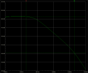
I did a preliminary sim of my circuit before a future testing to check the feasibility, I need to know if it is enough stable, how the thermal drift can change the biasing current of the output stage and possibly fix it.
if the circuit pass this test it 'would' be better for instance of any cmoy or O2 amp, with lower output impedance, lower distortion, lower noise but it needs more current because of its full class A design.
while I am waiting to receive toshiba bipolar from an ebayer seller to test my circuit, I am simulating another all class A topology, just a little bit stranger: this is the open loop gain of the whole amp, with 207 dB of gain @ 20Hz and 102 dB @ 20 Khz
hypothetically, if it is real what do I expect from this amp? does it sound better than conventional amp?

hypothetically, if it is real what do I expect from this amp? does it sound better than conventional amp?
Attachments
everything has its limits - feedback factor grossly exceeding your S/N is fairly useless, "costs" you in needing higher loop gain roll off rate, actually reducing available feedback factor at higher frequencies
http://trs-new.jpl.nasa.gov/dspace/bitstream/2014/19495/1/98-0905.pdf doesn't explain the noise limit but does show the basic "conservation law" of feedback
for headphones heavily biased output buffers can have few 0.1% "open loop" distortion, adding 80-120 dB loop gain likely gives as much performance as can be distinguished from system noise at audio frequencies - ears do not do 10s or 100s of seconds of averaging to reach down into the noise floor like we can with fft
my design has 102 dB @ 20 Khz open loop gain, I think no one opamp have the same gain. of course the stabilization network decrease available feedback factor but at higher frequencies, over 70-80 khz (in my design)....actually reducing available feedback factor at higher frequencies...
I agree, but since I had made and tested this network but without output stage many years ago, I think it could interesting to test the circuit by AP equipment and for sonic performance. don't you think it's a good idea?for headphones heavily biased output buffers can have few 0.1% "open loop" distortion, adding 80-120 dB loop gain likely gives as much performance as can be distinguished from system noise at audio frequencies - ears do not do 10s or 100s of seconds of averaging to reach down into the noise floor like we can with fft
Headamp
Please see here:
http://www.ac-vogel.de/TransBuffer_Artikel/TransBuffer_APN_1.html
This amp is tested by Audio Precision 2 and works with several Loads.
Don't forget heatsink
Please see here:
http://www.ac-vogel.de/TransBuffer_Artikel/TransBuffer_APN_1.html
This amp is tested by Audio Precision 2 and works with several Loads.
Don't forget heatsink
I just wanted to point out where there are limits and where there is real improvement – the “207 dB loop gain” isn’t a “real” improvement – emphasizing it may confuse/mislead the many here who haven’t mastered feedback theory
I certainly do think high loop gain feedback and composite amplifiers are great techniques, have built and verified some with distortion below –160 dB with an indirect IMD test and a Juli@ soundcard – a measurement that did take averaging to see into the noise may have a cool factor for feedback geeks but has little audio relevance beyond establishing that linearity for audio signals is not an issue
http://www.diyaudio.com/forums/soli...ain-composite-op-amp-circuits.html#post512806
do headphone amps count as the "real world" even in audio?
Bode linear stability of high loop gain amps is the initial challenge - very fast output devices help with this - DSL driver op amps seem perfect for many dynamic headphones and audio signal line driving with extended GBW that makes the CFA DSL drivers usable inside many "audio" op amp's feedback loop without difficulty
if you want to go further than Bode's "Maximal Feedback" ~ 30 dB/decade loop gain you encounter "conditional stability" - reduced gain from clipping, slew rate limiting can cause higher order roll off loop gain amps to have nonlinear oscillations - clamping diodes for internal nodes, limiting "wind up", other measures can help but the clipping recovery will often look worse than "simpler", "low gain" amps
for headphone amps it is easy to just have the headroom for driving your headphones to >120 dB SPL before clipping
B.J. Lurie's papers, books are a real help understanding this particular conrer of very high loop gain feedback - and they aren't perfect - "buggy" texts and sometimes hard to understand - but offering useful insights, perspectives I've never seen spelled out elsewhere
wthin the restricted setting of DSL op amp output V swing and current I would say these high loop gain/composite op amp techniques pretty much "solve" for any practical purpose the audio amplification “gain block” "problem"
but if you "dissect" "feedback amplifiers" by the block diagram you see that gain is only 1 of the 3 parts: gain, feedback and difference/sumer
feedback part selection is as open as your belief in part's "sound" but bulk metal foil R and polystyrene Caps have few measurable nonlinearities
the input sumer that differences the input and feedback signal to get the "error" that the gain block amplifies has limits
at low Z, low signal like MC phono cart some discrete designs can beat monolithic op amps on noise
there are common mode V nonliearities that are "outside" of the feedback loop - bootstrapped cascode diff pair like AD627 can help
RF rectification in input device nonlinearity is another concern - higher bias, bigger junctions can give discrete an advantage, fets supposedly are superior - but I've seen little on GHz input BJT with local degeneration, or comparisons with AD's new BJT input for AD8099, ADA4898
Last edited:

the basic "multiloop" with a high current fast unity gain buffer in the op amp loop is quite common, even in hobbyist diy headphone amps with discrete or integrated buffers
adding loop gain by making the "buffer" a CFA op amp with local "flat" gain, adding some loop gain, is described in Walt Jung's "Op Amp Applications" book and other articles so it is a practical engineering technique if a little more difficult than cookbook hobbyist level
the potential nonlinear oscillation/clipping recovery is something you can encounter in discrete circuits too but it will be new to most users used to single monolithic op amp circuits with dominant pole compensation - unity gain stable dominant pole op amps are designed that way because it makes them easy to use but does give up a little potential performance
it is the higher order loop gain shaping/rolloff that allows >100 dB loop gains to high audio frequencies where the complexity really steps up
Halcro's patents don't really "teach" the added nonlinear stability/clipping recovery details need to be successful at that level of complexity - but higher order loop gain composite/multiloop amplifier topology is a tool that can be used if "parts per billion" distortion numbers from the active components interests you
the "simple" "formula" of good "audio" op amp with a fast unity gain buffer in its feedback loop is probably a good trade off of minimal added complexity/design difficulty for most of the potential performance improvement
you still can use sub regualted input op amp rails, the composite amp breaks the thermal feedback of output stage heating to the input diff pair, the buffer presents such a high load impedence that the input op amp is working Class A driving the buffer input and you can use Class A output stage bias
Last edited:
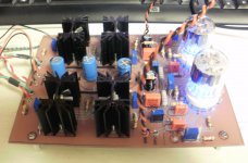
I prefer tube input and gain stages with Mosfet output in class A operation. The Mosfet takes care of the output drive for various impedance head-phones and the Mosfet has the same transconductance as a tube, Voltage in / current out....
Attachments
- Status
- This old topic is closed. If you want to reopen this topic, contact a moderator using the "Report Post" button.
- Home
- Amplifiers
- Headphone Systems
- Yet another simple class A headphone amp