Help! Excessive Low-Battery Shutdown Transient Voltage
Hello. I've built an Objective-2 amplifier by following all the official instructions two years ago, and it worked great. But recently I cleaned the dust off the PCB and re-performed the low-battery shutdown test to ensure Q1 and Q2 was not damaged in this process. I noticed something unusual, when I unplugged the battery on the left side, the O2 amplifier smoothly turns itself off without any noise, but unplugging the right-side battery resulted a more-than-moderate BANG on my 1-dollar earphone. I don't think I noticed this when I first tested it 2 years ago, so I believed the power management was somehow malfunctioned and could possiblely damage my actual earphone when in use, and I started to troubleshoot.
In the process I suspect one of the chip or MOSFET failed because of ESD, and I replaced Q1, Q2, U1, U2, U3, U4, but the BANG is still there when the right-side battery is unplugged. The amplifier didn't change much, it still plays music, and the usual sound for power up and power dump is normal, still a moderate pop when it's on and a little "glitch" when it's off, and all the in circuit measurement seems also unchanged.
Even the battery shutdown test is somehow okay, the output DC voltage quickly falls below 0.5 volts when either of the battery is disconnected and the two DC rail voltages also drops to nearly 0 volts. The only problem is when the right-side battery disconnects, a BANG sound appears in the 1-dollar garbage earphones (only for testing). But it is completely silent for the left-side battery disconnection, only the right-side has this problem.
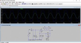
I hooked up my scope to the P2 test header to check the audio jack output, and the scope showed a shutdown transient around 1 - 3 volts of transient voltage within 5 milliseconds.
I'm running out of idea. What's going on?
Is it just normal for a low impedance cheap earphone and the BANG should not be heard on earphones with higher impedance? I don't think so because I didn't recall the BANG when I tested it 2 years ago.
Perhaps a filter/bypass capacitor failed? I checked C16 and C21 and the measurement still matches their labeled values in reasonable tolerance (0.22uF, 0.24uF for each vs. standard 0.22uF designed value). So the problem is in elsewhere.
Could anyone help me. Thanks.
Hello. I've built an Objective-2 amplifier by following all the official instructions two years ago, and it worked great. But recently I cleaned the dust off the PCB and re-performed the low-battery shutdown test to ensure Q1 and Q2 was not damaged in this process. I noticed something unusual, when I unplugged the battery on the left side, the O2 amplifier smoothly turns itself off without any noise, but unplugging the right-side battery resulted a more-than-moderate BANG on my 1-dollar earphone. I don't think I noticed this when I first tested it 2 years ago, so I believed the power management was somehow malfunctioned and could possiblely damage my actual earphone when in use, and I started to troubleshoot.
In the process I suspect one of the chip or MOSFET failed because of ESD, and I replaced Q1, Q2, U1, U2, U3, U4, but the BANG is still there when the right-side battery is unplugged. The amplifier didn't change much, it still plays music, and the usual sound for power up and power dump is normal, still a moderate pop when it's on and a little "glitch" when it's off, and all the in circuit measurement seems also unchanged.
Even the battery shutdown test is somehow okay, the output DC voltage quickly falls below 0.5 volts when either of the battery is disconnected and the two DC rail voltages also drops to nearly 0 volts. The only problem is when the right-side battery disconnects, a BANG sound appears in the 1-dollar garbage earphones (only for testing). But it is completely silent for the left-side battery disconnection, only the right-side has this problem.
I hooked up my scope to the P2 test header to check the audio jack output, and the scope showed a shutdown transient around 1 - 3 volts of transient voltage within 5 milliseconds.
An externally hosted image should be here but it was not working when we last tested it.
I'm running out of idea. What's going on?
Is it just normal for a low impedance cheap earphone and the BANG should not be heard on earphones with higher impedance? I don't think so because I didn't recall the BANG when I tested it 2 years ago.
Perhaps a filter/bypass capacitor failed? I checked C16 and C21 and the measurement still matches their labeled values in reasonable tolerance (0.22uF, 0.24uF for each vs. standard 0.22uF designed value). So the problem is in elsewhere.
Could anyone help me. Thanks.
Last edited:
I think the simple answer to this is that is normal.
The opamp audio circuitry is bound to jump to a relatively high DC level if a rail is suddenly disconnected. Its basically a non valid operating state.
Yes, higher impedance and/or lower sensitivity headphones would make the effect less apparent.
The opamp audio circuitry is bound to jump to a relatively high DC level if a rail is suddenly disconnected. Its basically a non valid operating state.
Yes, higher impedance and/or lower sensitivity headphones would make the effect less apparent.
I built the O2 few months ago. I found there are two problems and like to seek advice:
1. I noticed a "pop" sound when turning on and off the amp? Is it an expected behavior?
2. I noticed a noticeable distortion on high gain setting(R16/R22=1.5k, R19/R23=274). When switch back to low gain, it is better but still noticable if listen carefully. Is it due to the resistors value too small??
Noises at power on and power off are to be expected. It is the single real failing of the whole design imo.
The distortion sounds like you are overdriving the input. You could try increasing or even totally removing the 1k resistors (R17/R21). Removing them would drop the gain to '1'.
The gain is given by Gain = (R16/R17) + 1 assuming the 1k is switched into circuit.
So you have a gain of 2.5 at the moment.
Try something like a 3k3 to begin with and see if that improves things.
Noises at power on and power off are to be expected. It is the single real failing of the whole design imo.
The distortion sounds like you are overdriving the input. You could try increasing or even totally removing the 1k resistors (R17/R21). Removing them would drop the gain to '1'.
The gain is given by Gain = (R16/R17) + 1 assuming the 1k is switched into circuit.
So you have a gain of 2.5 at the moment.
Try something like a 3k3 to begin with and see if that improves things.
Thanks for your answer. But I am not understand why using small value pair of resistor will overload the input? Could you briefly explain?

AC-AC 12V 1A Adapter For Maxim MA411210 Class 2 Power Supply Cord Charger PSU | eBay
This one have same marking.
This one have same marking.
Hello,
I answered today to a similar question to a headfier: O2 AMP + ODAC | Page 369 | Head-Fi.org, hope that helps.
I've honestly no idea why would you need so much power to drive Fostex T50RP drivers, like Alpha Prime has inside; the scenario you speak about sounds more like HIFIMAN HE-5. Anyway, you could unplug the headphones and try playing a 0dB 1KHz wave file taken from Audiocheck website, then measure the headphone output with a multimeter to find out the exact voltage and gain your O2 is using. You'll need either to get O2's cover and measure directly on headphone's output plug, either to find a jack and wire it properly to get the output signal measured correctly (pay attention to any possible short-circuit you could cause).
Just listened now to Deep Purple - "Smoke on the water" with peaks getting at most to -3dB, with O2's gain set to 1X and volume potentiometer to the max. I felt that the volume was a bit too high for my ears. My O2 was feed by the ODAC that has a max. of 1.92V RMS on outputs. I was also testing the 3.5X gain, but after getting the pot. volume after 2 o'clock I wasn't feeling comfortable, so for feeding my Fostex T50RP MK3 from O2 amplifier even the low-gain of 1X can do the job for most music (depending on the dynamic range and volume of recording).
Best,
Raul.
I've been focusing on my stax system for awhile, but I picked up the Alpha Primes and o2 again, and I have a slightly different perspective now. The o2 sounds a lot better than I remembered, but they're still undoubtedly missing something. So to be exact, I know the Primes don't sound their best on the o2, and a lack of power is the only explanation I can think of that sounds plausible.
The way I--and other Alpha owners--hear it, the Alpha Prime will reach a good SPL even with low powered amps, but the bass will be more gently articulated than slamming with any force. At the same SPL using a powerful amp, the bass slams, and hard, without losing control. It's my favorite thing about them, really, and that's why it bothers me so much. The o2 doesn't deliver the most important part.
How can an amp play at the desired SPL without clipping, yet be underpowered all the same?
If that's not possible (considering the o2's performance in peak power, slew rate, etc), then how can I explain what I'm hearing/ mishearing?
How far can I ride this effect, whatever it is? Will there be a "slam ceiling" eventually?
 I've never tried anything bigger than 50wpc(@8ohms), would it slam even harder with 100wpc available? 500? (I'm joking about this last paragraph--the Schiit Magni 3 delivers the same amount of bass as the big speaker amps--but I'm serious about everything else)
Last edited:
After my diagnosis, my conclusion is the same, the transient voltage is completely normal before the shutdown circuit kicks in. But I still don't understand why it only occurs on BT2, perhaps the time difference of the two voltage rails and the tolerance of the MOTFETs I guess.
Thanks Mooly! It's really a supportive community.
Thanks Mooly! It's really a supportive community.
It is the kind of issue where you may find different opamp types behave a little differently, the noise may be better (or worse).
Also you have to remember that the headphones couple directly to the opamp output. and so any slight voltage change will appear very loud in the 'phones. Traditionally on many amplifiers there would be quite a high value resistor feeding the 'phones, and that would greatly minimise the noise.
Also you have to remember that the headphones couple directly to the opamp output. and so any slight voltage change will appear very loud in the 'phones. Traditionally on many amplifiers there would be quite a high value resistor feeding the 'phones, and that would greatly minimise the noise.
After my diagnosis, my conclusion is the same, the transient voltage is completely normal before the shutdown circuit kicks in. But I still don't understand why it only occurs on BT2, perhaps the time difference of the two voltage rails and the tolerance of the MOTFETs I guess.
Thanks Mooly! It's really a supportive community.
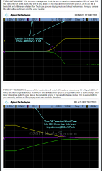
NwAvGuy did document throughly the transients, see the attached image
Attachments
Thanks CHiroshi.
Interesting, and that reafirms my view that this this is a poor aspect of the design. I'm pretty sure some effective muting could be employed as an add on, perhaps using a discrete FET relay that is held 'on' all the time by the + battery supply, and that gets turned off when the negative rail appears (after a short delay).
Quoting 600 ohms is a bit misleading because the same 800mv will appear across load impedances down to single figures. 800mv across 8 ohm is probably just about within the current ability of the parallel opamp output stage, and that will sound very loud indeed.
Yeah, the answer is agdr's booster board!Thanks CHiroshi.
Interesting, and that reafirms my view that this this is a poor aspect of the design. I'm pretty sure some effective muting could be employed as an add on, perhaps using a discrete FET relay that is held 'on' all the time by the + battery supply, and that gets turned off when the negative rail appears (after a short delay).
Quoting 600 ohms is a bit misleading because the same 800mv will appear across load impedances down to single figures. 800mv across 8 ohm is probably just about within the current ability of the parallel opamp output stage, and that will sound very loud indeed.
O2 headamp output booster PCB
- Home
- Amplifiers
- Headphone Systems
- The Objective2 (O2) Headphone Amp DIY Project