Scratching my head 1
Thanks for your previous reply Mooly! I appreciate it.
Following your guide I don't get further than "Checking the output of the regulators".
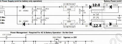
The DC voltage on the striped end of D1 is 12.8 V.
And the DC voltage on the NON striped end of D5 is - 12.8 V.
So then the problem is the regulators right?
Could you tell how to check the regulators?
Thank you
Thanks for your previous reply Mooly! I appreciate it.
Following your guide I don't get further than "Checking the output of the regulators".
The DC voltage on the striped end of D1 is 12.8 V.
And the DC voltage on the NON striped end of D5 is - 12.8 V.
So then the problem is the regulators right?
Could you tell how to check the regulators?
Thank you
Those readings are fine. Plus 12.8 on D1 and -12.8 on D5 as shown here. Those voltage should then carry through and be the same on pin 8 (+12.8 volts) and pin 4 (-12.8 volts) on U2.
Do you mean they are just fractionally high ? That's no problem as they are not absolute values. The regulators have a tolerance and are not exactly 12.00 volts.
Do you mean they are just fractionally high ? That's no problem as they are not absolute values. The regulators have a tolerance and are not exactly 12.00 volts.
Attachments
Scratching my head 2
Hi Mooly, the values were just fractionally high indeed. And they did carry through to Pin 4 and 8 on U2.
Then going on to rough test the comparator, I soldered a short over R9. Put in U1 and left in U2
And the values I measured over U1, U3 and U4 for Pin 4 was 0.3 V and for Pin 8 it was 0.02 V. Since it should fall to zero, do you have any advice?
Thank you in advance
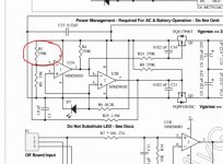
Shorting R9 flips the comparator state such that both FET's are off which means that the supplies are disconnected from the following circuitry.
I suspect you are seeing residual charge on capacitors C8 and C9 rather than a true problem. Lol, I can see I am going to have to alter the wording in the faultfinding guide")
However with R9 shorted you should also read approximately +12 volts on pin 1 of U2 and - 12 volts on pin 7. In that state the FET's are off.
With R9 not shorted the above voltage should flip giving -12 on pin 1 and +12 on pin 7 which will turn on the FET's. You should also then see the supplies make it through to the remaining empty IC sockets giving +12v on pin 8 and -12 on pin 4.
I suspect you are seeing residual charge on capacitors C8 and C9 rather than a true problem. Lol, I can see I am going to have to alter the wording in the faultfinding guide
However with R9 shorted you should also read approximately +12 volts on pin 1 of U2 and - 12 volts on pin 7. In that state the FET's are off.
With R9 not shorted the above voltage should flip giving -12 on pin 1 and +12 on pin 7 which will turn on the FET's. You should also then see the supplies make it through to the remaining empty IC sockets giving +12v on pin 8 and -12 on pin 4.
The supplies getting through are the main thing at this point. At face value I would have thought pin 1 would swing between + and - 12 volts. We'll perhaps come back to that one later although the fact the supplies are correct is sufficient to carry on.
Perhaps anyone reading this and who has an 02 could confirm what the voltage really is on pin 1 of the comparator
(I often mention in the thread that I have actually never even seen an 02, let alone built and listened to one, and so all the descriptions I give are based on pure theory and working from the circuit diagram)
So the supplies are present. What I would do now is fit both U3 and U4. Power the 02 up and recheck that the supplies are still correct on pins 4 and 8 of both those IC's. All the other pins should (and must) be close to zero volts. Close here means just a few millivolts at most.
Kind of done scratching my head.
I did put in U3 and U4 and the supplies are correct on pins 4 and 8 after power up. All the other pins are zero Volts.
I then gave it a try and put in some headphones. And connected it to my Ipod. And music comes out! Though a bit distorted...
Do you by any chance have any advice on that?
And thank you for your time and advice so far. Even though it's theory. It does seem to work.
So... with U1not fitted there definitely should not be any audio present. The fact that you have suggests a physical construction error or issue somewhere. Lets look at one channel.
If you look at the circuit and imagine we are working back from the headphone socket toward the input, then the audio path should be 100% broken by removal of U1.
The only 'possible' path via R16/C19 isn't valid because they simply terminate via R17/19 to ground via the switch. So your audio is coming via what can only be some physical issue somewhere.
So first question is whether the volume control alters the distorted audio correctly and does in fact fully turn down to zero.
Scratching my head 4
My bad Mooly, I should have mentioned I left U1 still in place from the "rough test of the comperator". Sorry. Then I removed the short over R9 and put in U3 and U4.And the supplies were correct on pins 4 and 8 after power up of both U3 and U4. All the other pins were zero Volts.
Then I gave it a try with my ipod and got sound. Though distorted and a bit soft.
Any chance on advice on how to solve the distortion/volume?
Sorry for the confusion and thank you for the help so far!
No problem
Have you tried another signal source beside your iPod ? I'm not familiar with the iPod and so don't know if it has a dedicated line output or whether you are using the headphone out. Some headphone outputs can be poor at low volume and so you should at least try turning the iPod volume up if that is how you are using it. Trying a totally different source would be good for elimination purposes though.
If the issue of distorted sound really is with the 02 then the next simply step is to remove U1 and then link (just push bits of wire in the socket) pin 5 to pin 7 and pin 3 to pin 1. That 100% eliminates the first stage and should pass audio directly to the headphone driver stage of U3 and U4.
Try another source first though.
Edit... and also make sure the 1 ohm resistors on the output of U3/4 really are 1 ohm and not something like 1k.
I think I'm done scratching my head.
Hey Mooly,
I decided to give it another try without changing anything and again with my Ipod classic. And it worked fine this time.
For the next step I'm going to put in the rechargeable batteries.
And after that test it with the new headphones that are coming my way.
But I don't expect any troubles with that.
Thank you for the time and effort you've put in replying so far!
I really do appreciate it!
And just curious, what did you study or do, so that you can figure this all out from just theory?
Well thanks for the kind words, but as to it done, ah, well that would be telling
Actually there are no easy shortcuts I'm afraid, and for me it was a career in electronics. You have to first of all understand the basics, and then as that becomes second nature you find circuits such as the 02 fall into neat separate building blocks.
Actually there are no easy shortcuts I'm afraid, and for me it was a career in electronics. You have to first of all understand the basics, and then as that becomes second nature you find circuits such as the 02 fall into neat separate building blocks.
O2 R5 Wrong Measurements
Hello all, I hope I'm in the right place.
I recently bought an O2 kit from JDS Labs and was hoping that you guys could help me out. I've soldered everything onto the circuit board and am now testing all of the resistors. Every resistor has measured the right amount resistance except for R5. NwAvGuys diagram says that R5 is supposed to have 100 k ohms, but the resistor that JDS Labs sent for R5 has a color code for a 270 k ohm resistor (see picture). When I measure the resistor when it's in circuit it measures at about 235 k ohms, and when I measure it out of the circuit it reads 270 k ohms, which matches the color code. JDS Labs picture of the completed O2 kit seems to show that the same resistor in their photo is what they sent. Has anybody had any experience with this problem? Any help will be appreciated.
Thank you.
Attachments
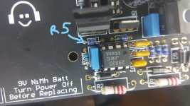
My diagram shows it as 270k.
Checking resistors in circuit is poor practice because they interact with all the other components giving misleading readings.
The Objective2 (O2) Headphone Amp DIY Project
Checking resistors in circuit is poor practice because they interact with all the other components giving misleading readings.
The Objective2 (O2) Headphone Amp DIY Project
Attachments
A bit of a side-grade mod that I find works well for the o2 is to use ADA4075-2 for U1 and LM4565 for the power buffers, drops the opamp quiescent consumption by about half. Certainly not as dramatic as the original 'low power' recommendation but preserves pretty much all of the original traits of the o2 and doesn't cost much at all.Nothing radical in here, just some minor part improvements due to new parts that have become available since that O2 BOM was released back in 2011. The 9th item in there lists the part numbers at Jameco for the O2 AC-to-AC transformer (they have a couple of good choices).
The ADA4075-2 is a touch stronger than the NJM2068 so the mid-low loading the o2 was designed with actually happens to be optimal. I haven't tested the LM4565 for full range stability, but seems to perform solidly as a power buffer. In my tests it seems that the NJM4556 still has a outright stronger drive but not by much.
Although having improved the battery life I still don't use the o2 as a true portable, but the reasons for that are more of a systemic issue.
A bit of a side-grade mod that I find works well for the o2 is to use ADA4075-2 for U1 and LM4565 for the power buffers, drops the opamp quiescent consumption by about half.
Interesting! I haven't heard of either chip. Just looked them up. That ADA4075-2 is certainly an interesting chip. Low noise and low THD. I can't find the LM4565 for sale here in the states, but looks like NJM has a version, the NJM4565.
Both Digikey and Mouser have them in stock.
Sure enough, looks like I scrolled through the search results list too fast on Mouser:
LM4565F-GE2 ROHM Semiconductor | Mouser
and the datasheet (opens PDF)
http://www.mouser.com/ds/2/348/lm4565f-e-372180.pdf
- Home
- Amplifiers
- Headphone Systems
- The Objective2 (O2) Headphone Amp DIY Project