I don't have a bookcase, but I do have a benchcase
Wow- what a setup! I'm too embarrassed to show my bench case. Maybe I will PM you my setup snaps
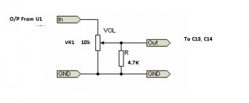
This can't work, you just increase the load of the preamp. You have to create a voltage divider somehow.
Sorry for the unintended confusion.
With 4.7K (connected from centre to gnd of pot)
You get 3.2K pot
With 10K
You get 5K pot
With 40.2K
You get 8K pot
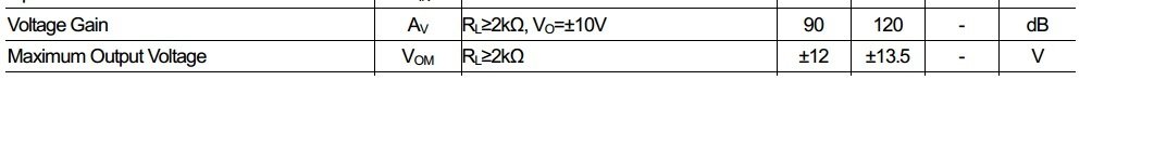
All combinations are above JRC 2068 lowest RL limit of 2K.I would highly recommend 10K as you may have extra pair in hands from BOM.No harm in trying. If this doesn't works for you can always clip the resistors.
BTW pot linearity will be thrown out of window.
Pls refer to attch. schematic.
Attachments
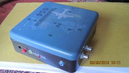
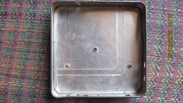
O2 with stepped attenuator
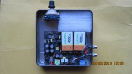
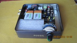
Here are some photographs of my "Fossilised" O2 with stepped attenuator(11+1 steps)
PCB is mounted on brass studs separated by anti-static plastic sheet from the main body to prevent any accidental shorts. It has RCA i/p which are automatically disabled when 3.5mm i/p connector is inserted from front panel. The bare outer ring of RCA i/p connects i/p Gnd. to tin box reducing noise. Jumpers are used instead of gain switch giving me 3 gain options(1X,2X,8X).
Resistor values used in stepped attenuator 100,180,390,680,910,1K,1.2K,1.5K,1.8K,2.2K,2.7K (hand-matched).
It gets comfortably loud at 1X gain with RCA i/p from consumer DVD player , 2X from my laptop & 8X from ipod touch for my Superlux HD668B(56 Ohms, Sensitivity 98dB)
The vacant space(foam)will be used for installing DC protection relay circuit & 1/4" socket. Non-standard red LED used (fwd. drop of 1.78V) with R6 (33K) as suggested by agdr. PM circuit works like a charm.
Attachments
Last edited:
Sorry for the unintended confusion.
With 4.7K (connected from centre to gnd of pot)
You get 3.2K pot
With 10K
You get 5K pot
With 40.2K
You get 8K pot
All combinations are above JRC 2068 lowest RL limit of 2K.I would highly recommend 10K as you may have extra pair in hands from BOM.No harm in trying. If this doesn't works for you can always clip the resistors.
BTW pot linearity will be thrown out of window.
Pls refer to attch. schematic.
This does not work that way. You basically would get another taper characteristic and an uneven load with this. Mostly it would just attenuate the higher gain settings. With 4.7k parallel and the volume at 50% you would get about 16% less voltage which would just be 0.75dB at lower gain settings it is even less than that.
Hi! Im having tome trouble to find some parts here in Argentina.
What if on C13 and C14, instead of the Metal Film Polyester BOX capacitor i just use regular Metal Polyester ones like in the picture above?
http://theonlinetutorials.com/theonlinetutorials_files//2011/04/PolyesterFilmCapacitor1.gif
Will this change the operation of the amp? Change the sound of it?
Im the kind of person that chooses Rubycon caps over no brand caps , i think that matters.
And concerning the potentiometer , i cant get anything better than this.
http://www.onlinetps.com/shop/images/item_images/Dual_Potentiometer.jpg
How much matters if i use a cheap chinese pot instead Alps or Bourns ?
Cheers , Stefano
This does not work that way. You basically would get another taper characteristic and an uneven load with this. Mostly it would just attenuate the higher gain settings. With 4.7k parallel and the volume at 50% you would get about 16% less voltage which would just be 0.75dB at lower gain settings it is even less than that.
Yes you are right on "uneven load" as seen by 2068 with added non linearity issues, but I've seen those type of implementation in electronic fan regulators
Chk this for more info
ESP - A Better Volume Control
BTW What is your music source? Can't you control vol. from there?
Last edited:
...Will this change the operation of the amp? Change the sound of it?
Im the kind of person that chooses Rubycon caps over no brand caps , i think that matters.
How much matters if i use a cheap chinese pot instead Alps or Bourns ?
I'm no expert on caps, but you will have hard time physically fitting non-standard BOM components. Believe me I've done that.
As for pot-don't even bother with cheap Chinese dump, you can short appropriate holes giving you full vol. from O2 & you can control your vol. from your source with its own digital vol. control(far better tracking than Alps or Chinese pot). Above all when those Chinese pot. wear out, you will have hard time de-soldering again.
See attch. for my implementation
Attachments
Last edited:
Finished my third O2+Odac combo today. Set a new personal speed record too, total build time was about three hours I think.
I have a step-by-step construction guide coming up on my blog within the coming days.
Congrats-Keep up the good work. I read your blog, it reminded me of my school days when I had to borrow soldering iron from my friends to solder my broken h/p wires. Hope you build more such projects to finance your purchase of much needed measuring instruments.
Cheers!
Last edited:
I'm no expert on caps, but you will have hard time physically fitting non-standard BOM components. Believe me I've done that.
As for pot-don't even bother with cheap Chinese dump, you can short appropriate holes giving you full vol. from O2 & you can control your vol. from your source with its own digital vol. control(far better tracking than Alps or Chinese pot). Above all when those Chinese pot. wear out, you will have hard time de-soldering again.
See attch. for my implementation
I know the non-standard BOM cap is larger , but i won't be using the official aluminium enclosure so that is not a problem. Your volume implementation is very clever
, but does not suit for me , since i will connect the iPod Touch with a Line Out cable (3.5mm to 30pin Apple connector) , so the signal is sent at full vol. so i need to change it on the amp.Thanks for your reply availlyrics
So besides the physical SIZE problem , can i use polyester caps without worrying about performance?
Congrats-Keep up the good work. I read your blog, it reminded me of my school days when I had to borrow soldering iron from my friends to solder my broken h/p wires. Hope you build more such projects to finance your purchase of much needed measuring instruments.
Cheers!
Thanks!
Yes, in the beginning I had to borrow equipment from a neighbour. Last xmas my parents gave me my own soldering equipment so now I'm hoping to get enough customers to buy a better multimeter and some other stuff that's good to have.
...So besides the physical SIZE problem , can i use polyester caps without worrying about performance?
Go ahead with whatever is available locally,its better than using no-caps resulting large DC
BTW Gaincard by 47 labs uses 4.7 uF electrolytic i/p caps(I've read somewhere).
Here's a O2 powering PA spk. crazy
Objective 2 powering PA speaker - YouTube
Pls don't try this stunt on your B&W Nautilus
Objective 2 powering PA speaker - YouTube
Pls don't try this stunt on your B&W Nautilus
Thanks NwAVGuy, what a sweet package
Hey Guys, just want to share with you my accurate, none snaked oil HiFi environment, which - unfortunately for the notorious extravagant high end industry - wasn't too pricy.
@ Engineer - where have you been? People need sane, down to earth discussions so they do not get detached
KR
Tobias
Hey Guys, just want to share with you my accurate, none snaked oil HiFi environment, which - unfortunately for the notorious extravagant high end industry - wasn't too pricy.
An externally hosted image should be here but it was not working when we last tested it.
@ Engineer - where have you been? People need sane, down to earth discussions so they do not get detached
KR
Tobias
Help!
Just built another O2 amplifier. Everything went smoothly except that I accidentally put a resistor in the wrong place but I fixed that before powering it up. Also the gain switch wasn't in a good position so I had to force it down a bit while heating up the joints.
Measured all voltages as the guide says and everything seemed fine.
Powered it up, connected a source and a pair of scrappy headphones. Expected it to work as it usually does but the sound was really distorted. Tried the headphones directly to my phone and then it sounded ok. I expected the gain switch to be the fault because it was a bit glitchy and I assumed I maybe broke it when pushing it down a bit. I have now removed it, it's broken to 1000 pieces and the sound is still as distorted as before.
I have checked the voltages at D1 and D5 and all seems fine.
Edit!
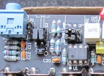
"Check pin 1 and pin 7 of U1. Both should be under 0.1 volts. If either is higher, check the pins of P1 with your source connected and turned on. There should not be more than +/- 0.02 volts at any of the P1 pins. If so, there’s a problem with your source. If P1 is OK, but pin 1 and/or 7 of U1 has significant DC, U1 is somehow developing a DC offset and either U1 is bad or there’s a soldering problem with it or all the parts around it."
Did this and when measuring from negative bt1 to pin 1 and 7 of U1 I between 200-350mV peaking at about 400mV. Is U1 faulty then? I see no solder bridges and I have reheated all the joints.
Please help me. This isn't my amplifier, I'm building it for someone else.
Edit2:
I have another JRC2903D because I have two sets to build. Shall I try with a "fresh" U1? Or is there a risk that I'll trash both because there's something wrong with the board?
Just built another O2 amplifier. Everything went smoothly except that I accidentally put a resistor in the wrong place but I fixed that before powering it up. Also the gain switch wasn't in a good position so I had to force it down a bit while heating up the joints.
Measured all voltages as the guide says and everything seemed fine.
Powered it up, connected a source and a pair of scrappy headphones. Expected it to work as it usually does but the sound was really distorted. Tried the headphones directly to my phone and then it sounded ok. I expected the gain switch to be the fault because it was a bit glitchy and I assumed I maybe broke it when pushing it down a bit. I have now removed it, it's broken to 1000 pieces and the sound is still as distorted as before.
I have checked the voltages at D1 and D5 and all seems fine.
Edit!
"Check pin 1 and pin 7 of U1. Both should be under 0.1 volts. If either is higher, check the pins of P1 with your source connected and turned on. There should not be more than +/- 0.02 volts at any of the P1 pins. If so, there’s a problem with your source. If P1 is OK, but pin 1 and/or 7 of U1 has significant DC, U1 is somehow developing a DC offset and either U1 is bad or there’s a soldering problem with it or all the parts around it."
Did this and when measuring from negative bt1 to pin 1 and 7 of U1 I between 200-350mV peaking at about 400mV. Is U1 faulty then? I see no solder bridges and I have reheated all the joints.
Please help me. This isn't my amplifier, I'm building it for someone else.
Edit2:
I have another JRC2903D because I have two sets to build. Shall I try with a "fresh" U1? Or is there a risk that I'll trash both because there's something wrong with the board?
Last edited:
I would suspect the 2068 to be the culprit, had that before as well.
Good luck, Stefan
Tried with a new fresh one. Same problem.
Edit: Oh god what an idiot I am! I had mixed up U1 and U2 so the 2903 was U1 and the 2068 was U2. Put them back correctly and now everything works as a charm. The only problem is I have trashed the gain switch by prying it loose from the board because I thought it was faulty. Is it some sort of standard component that I can find locally in Sweden? Or it is something that can be left off the board?
I don't know about parts availability in Sweden, but you can leave it off the board. Just pick what gain you want (no switch = no switchable gain) and jumper the connections. Use a cutoff component lead or piece of solid copper wire and it will be easy to remove and install a new switch at a later date.
I don't know about parts availability in Sweden, but you can leave it off the board. Just pick what gain you want (no switch = no switchable gain) and jumper the connections. Use a cutoff component lead or piece of solid copper wire and it will be easy to remove and install a new switch at a later date.
Is it even necessary to jumper the connections? I have installed the standard gain resistors and now without the switch gain seems to be 2.5x. Might be 1x too though, not sure.
- Home
- Amplifiers
- Headphone Systems
- The Objective2 (O2) Headphone Amp DIY Project