@xaurot
I will be testing a replacement MOSFET for Q2 in about two weeks, and will let you know if it fixes the problem I am seeing.
@jayce996
Have you looked on eBay? The O2 BOM lists alternative part numbers which you might be able to find with cheaper postage on the bay.
I will be testing a replacement MOSFET for Q2 in about two weeks, and will let you know if it fixes the problem I am seeing.
@jayce996
Have you looked on eBay? The O2 BOM lists alternative part numbers which you might be able to find with cheaper postage on the bay.
Hi,
if you need single spare parts you can also shoot me a PM, I buy all the parts in high quantities and am able to offer them to you at lower prices than mouser farnell & co. if single parts are required. Postage will be moderate is sent by letter mail in a bubble envelope")
Stefan
if you need single spare parts you can also shoot me a PM, I buy all the parts in high quantities and am able to offer them to you at lower prices than mouser farnell & co. if single parts are required. Postage will be moderate is sent by letter mail in a bubble envelope
Stefan
I need some clarification on RS's low power option which I intend to build next. He writes :
"You might also consider doubling the values of all six gain resistors and cutting the compensation capacitors in half to reduce the loading on the first stage."
All six gain resistors? I thought there were only four. Looking at the BOM I can see R3, R7, R19, R23, R17 and R21 are mentioned in some respect to gain resistors. Are these the ones? I know it seems obvious but I've learned the hard way not to make optimistic assumptions.
The compensation capacitors: I have no idea what these are. Which C numbers are we talking of here?
thanks
You've got 6 gain resistors because there are two gain settings.
Rf = R16/22
Rg = R17/21 + R19/23
The caps are C19/20, in parallel to R16/22. Aim for same RC time constant.
An exact factor of 2 probably won't be feasible, but 2.2 should be.
BTW, I would actually recommend doing this. Low-power parts tend to have current-starved output stages which will be happier when loaded less. Gain stage noise usually is significantly attenuated anyway.
Last edited:
I know you already know this, but you'd be better off referring to the schematic instead of the BOM. Some of the resistors "are mentioned in some respect to gain resistors" on the BOM only because they are the same value. The gain resistors are R16, R17, R19, R21, R22, and R23. The compensation capacitors are C19 and C20.
Where do you guys buy 15-20V AC adaptor(EU plug preferable)? Anyone got a link to one that works with the O2?
Edit: Found one: http://www.kjell.com/sortiment/el/s...ac/ac-ac-transformator-18-v-ac-1000-ma-p44208
18V or 15V, the same or would 18V give more power?
Edit: Found one: http://www.kjell.com/sortiment/el/s...ac/ac-ac-transformator-18-v-ac-1000-ma-p44208
18V or 15V, the same or would 18V give more power?
Last edited:
I know you already know this, but you'd be better off referring to the schematic instead of the BOM. Some of the resistors "are mentioned in some respect to gain resistors" on the BOM only because they are the same value. The gain resistors are R16, R17, R19, R21, R22, and R23. The compensation capacitors are C19 and C20.
Thanks for that sgrossklass and Sofaspud.
In the meantime I'm listening, on my bed in my dimly but warmly lit room, to my O2+Odac with a nice bourbon and the 800 CD collection of my off-the-beaten-track-musical-taste flatmate. Here's raising a glass to Wigwam "Dark Album" which I've just happily barged in to.
Attachments

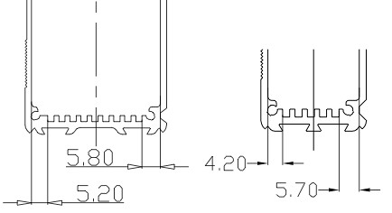
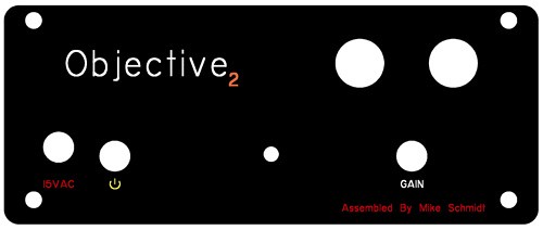
Are there any differences in the B2 and B3 enclosure other than the height? Is the PCB the same hight from the bottom of the enclosure on both cases? I'm looking to order a custom front panel for a B3, and am wondering if I just increase the height of the template for the B2 enclosure in the FPE software if it will fit the input/output etc correctly?
For a higher impedence headphone, like senn 650's, what would be a good gain for desktop only?
If in desktop mode it will only be playing from sources that are ~2V in output, then you will hit max power handling on the HD650 at a gain of 2.6x hence the use of 2.5x low gain by default. RocketScientist uses the HD650 as his go-to headphones.
Are there any differences in the B2 and B3 enclosure other than the height? Is the PCB the same hight from the bottom of the enclosure on both cases? I'm looking to order a custom front panel for a B3, and am wondering if I just increase the height of the template for the B2 enclosure in the FPE software if it will fit the input/output etc correctly?
There is a slight (~.9 mm higher iirc) difference in the height of the bottom of first slot from the base of the case.
Last edited:
Ok, my amp works great but I got this problem:
13. U2 Pin 1 (Q1 gate pull down) – Should be –11.8. If this is wrong but pins 2 and 3 above are correct U2 may be bad, the wrong part, or not installed correctly. Or there’s a nearby solder problem.
-11,7
14. U2 Pin 4 (negative supply) – Should be –11.8
-11,71
15. U2 Pin 5 (voltage reference) – Should be –10 (same as pin 3)
-9,94
16. U2 Pin 6 (same as pin 1) – Should be –11.8 (same as pin 1)
-11,7 (Pin1 -11,7)
17. U2 Pin 7 (Q2 gate pull down) – Should be around 6 to 11.8 volts (9,8 on my board). If it’s much below 6 positive volts, or worse a negative voltage, but pins 5 and 6 are correct, most likely Q2 has been damaged and the gate is pulling pin 7 too far negative. The other possibility is R8 or U2 (see pin 1).
8,48
For me the above results looks good, i've checked over the components and they are all in the correct places, I've also done the Initial DIY Testing.
Any ideas to other test I could do to find the problem?
LOUD TURN ON TRANSIENT: A few have reported this problem and it’s so far been Q1 and/or Q2 are damaged. Check the U2 pin 1 and pin 7 voltages outlined in steps 13 and 17 later in this section. And repeat the battery removal test in the DIY Testing section. It’s likely Q1 and/or Q2 are either stuck on or no longer working in sync with each because one is damaged. It’s also possible C16, C21 and/or C1 are missing, not soldered correctly, or the wrong value. Before replacing Q1 or Q2 see Circuit Board Construction regarding static precautions and be extra careful with the new parts.
13. U2 Pin 1 (Q1 gate pull down) – Should be –11.8. If this is wrong but pins 2 and 3 above are correct U2 may be bad, the wrong part, or not installed correctly. Or there’s a nearby solder problem.
-11,7
14. U2 Pin 4 (negative supply) – Should be –11.8
-11,71
15. U2 Pin 5 (voltage reference) – Should be –10 (same as pin 3)
-9,94
16. U2 Pin 6 (same as pin 1) – Should be –11.8 (same as pin 1)
-11,7 (Pin1 -11,7)
17. U2 Pin 7 (Q2 gate pull down) – Should be around 6 to 11.8 volts (9,8 on my board). If it’s much below 6 positive volts, or worse a negative voltage, but pins 5 and 6 are correct, most likely Q2 has been damaged and the gate is pulling pin 7 too far negative. The other possibility is R8 or U2 (see pin 1).
8,48
For me the above results looks good, i've checked over the components and they are all in the correct places, I've also done the Initial DIY Testing.
Any ideas to other test I could do to find the problem?
Guys, I just built an O2 and when checking the resistances with U2 in its socket, I get around 235K instead of ~100K for R5 as mentioned in the testing section, any ideas ? Rest of all the other values checks out right except for R8 which instead of ~245K, it measures 235K. I raised the resistors and measured them and they both show their original values (270K). I ploughed through either ways and connected the transformer a 12V 1.6A (with the S1 off ) affair and found that the voltage between BT1+ and BT2- measures 12V which is nowhere near 23-24V as mentioned in the DOC... any ideas ? I rechecked the soldering and found no visible bridges or dry soldering. I am not new to soldering but a bit rusty on the debugging side, any help is appreciated.
- Home
- Amplifiers
- Headphone Systems
- The Objective2 (O2) Headphone Amp DIY Project