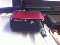
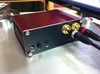
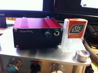
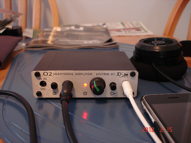
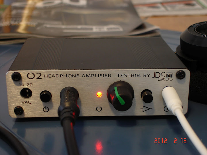
Pics of the o2 i built today for a customer. Nothing special inside except I used sockets for solderless gain changes
the outside I used some stainless hex socket cap screws and a black metal knob. The back RCA is gold plated.
-joe
the outside I used some stainless hex socket cap screws and a black metal knob. The back RCA is gold plated.
-joe
Attachments
R1 & R2
Greetings to all. New guy here. Caught the DIY bug with this amp. So thanks much for any help.
I am looking to use 300mah 9v batteries (unless there are higher capacity battery options) and I'm considering changing the values of R1 & R2 as discussed in the blog with a 150ohm value..
My questions are:
Is it that slow to charge using the default value(220 ohm)? How long does take to charge?
Will going to the 150 ohm value be that much faster?
Do I have to worry about over charging with the 150 ohm value?
What is the longest the O2 should be plugged in for with 150 ohm value?
Also could I use the SIP sockets used in the gain resistors for R1 & R2?
I just finished my O2 build and it went surprisingly well! All of the resistances checked out and most of the voltages did too from the testing section of the O2 details page. I first used a pair of Apple earbuds to test the amplifier and the sound was hollow and lifeless, but then realized that the earbuds had to be pulled out of the jack by ~1mm before it made proper contact. The O2 sounds amazing and I can't wait to try it with my better headphones soon.
During testing, I noticed that the voltages on pin 4 and pin 8 of U2 were slightly different when powered up with the power adapter. Pin 4 measured around -11.55 - 11.6 V while pin 8 was ~11.7 V. I used the standard O2 BOM and did not notice any obvious solder bridges. Is this indicative of an issue with the build or is it a result of variation in parts, etc?
During testing, I noticed that the voltages on pin 4 and pin 8 of U2 were slightly different when powered up with the power adapter. Pin 4 measured around -11.55 - 11.6 V while pin 8 was ~11.7 V. I used the standard O2 BOM and did not notice any obvious solder bridges. Is this indicative of an issue with the build or is it a result of variation in parts, etc?
I'm still looking for a good dac to pair with my o2, and I was wondering if anyone had some opinions on the Audioengine D1?
I'm still looking for a good dac to pair with my o2, and I was wondering if anyone had some opinions on the Audioengine D1?
Here is RocketScientist's take on it: NwAvGuy: ODAC Update
")
O2 The Basic Utility Version
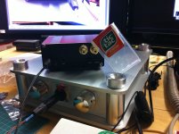
I needed to find a good solution for a simple, basic, and quality headphone amp. to use with my computer music and videos. I have a headphone amp. (AMB Beta 18) (with a real common ground) for the music server in the living room. I needed something for the bedroom system. I'm currently using an Audiotrak HD2 for the bedroom system that has a pretty good dedicated headphone amp. section. I noticed that the line out section had a cleaner output than the headphone amp but was not capable of driving the headphones very loud. I had a bunch of left over parts from various audio projects and decided to build a very basic version of the O2 for this application.
This may offend the sensibilities of some of you O2 purists. The amp. is built and hard wired on a left over Radio Shack perf board. Since part of my job is building test circuits on perf boards, this was right up my alley. The 4556 output opamps are mounted on a shared ic socket. I had a left over Marchand PS-10 regulated supply that I converted to 12 volt operation and it handles driving this amp. with ease. The cases are some rather utility, ancient Radio Shack left-overs.
This amp. has a surprising amount of power and control over my Sennheiser HD 580's. Definitely cleaner than the already pretty good Audiotrak on board amp. I'm driving the O2 with the line level output section from the Audiotrak. I also had a chance to drive it with my music server Acam-rdac DAC with very impressive results. Gain is set at 2.5X. This seems to be a good balance. There is no volume control as it is set with a 10K bridge resistor to simulate a wide open volume control. Volume is controlled with the HD2 interface or the media player volume control. No volume tracking error. The DC Level measured at the output was 3.2 mv. per channel. The output seen on my scope showed no oscillations and looks dead quiet. This amp. is extremely clean and quiet. I'm impressed!
Nice work, a1095us,
thank you. I like those basic designs. And never have seen those "shared ic socket", good idea! But aren't you afraid of burning your headphones with DC without the protection circuit? I planned something you did a few weeks ago, but was warned to do here: #2143
thank you. I like those basic designs. And never have seen those "shared ic socket", good idea! But aren't you afraid of burning your headphones with DC without the protection circuit? I planned something you did a few weeks ago, but was warned to do here: #2143
What I meant by shared IC socket was nothing more than an 18 pin socket that mounts both 4556's. I am not using batteries or the battery charging circuit. I'm just utilizing the basic Op-amp circuit with my out-board regulated supply. No burning headphones here! I do remember to plug in the phones after power-up and remove them before power down. My power up spike measured a little lower than NwAvGuy's.Nice work, a1095us,
thank you. I like those basic designs. And never have seen those "shared ic socket", good idea! But aren't you afraid of burning your headphones with DC without the protection circuit? I planned something you did a few weeks ago, but was warned to do here: #2143
Welcome to diyAudio.Greetings to all. New guy here. Caught the DIY bug with this amp. So thanks much for any help.
There's virtually always options. I'd need to refresh my memory as to just what NwAvGuy wrote about them.I am looking to use 300mah 9v batteries (unless there are higher capacity battery options) and I'm considering changing the values of R1 & R2 as discussed in the blog with a 150ohm value..
Before addressing your questions, I'd like to simplify things a bit by setting the regulated output at 12V, the shutoff at 6V, and the fully charged battery at 9V. And ignore the voltage drops of the steering diodes.
The O2 has no provision for fast-charging batteries. At a 1/10th charge current it will take roughly 12-15 hours to fully charge (there's always losses, so it isn't simply 10 hours).My questions are:
Is it that slow to charge using the default value(220 ohm)? How long does take to charge?
Not really enough to be significant.Will going to the 150 ohm value be that much faster?
Possibly. The usual target is 1/10th primary charge current, and a 1/20th maintenance charge current. 300mA divided by 20 equals 15mA, while 3 volts divided by 150 ohms equals 20mA. (This is where I'm using the parameters I mentioned at the beginning.)Do I have to worry about over charging with the 150 ohm value?
I wouldn't worry for the first 10-12 hours. I'd definitely check them then to see if they're getting too warm.What is the longest the O2 should be plugged in for with 150 ohm value?
Batteries that aren't made to fast-charge usually don't like to be fast-charged.
Not a problem.Also could I use the SIP sockets used in the gain resistors for R1 & R2?
Ideally, one wants to match the resistor value with the charge requirements of the battery (ie not those of the user, which is the undertone of your post IMO). You could obtain the real numbers for your situation to arrive at more accurate answers. But as it is, the only way to fast charge the O2 is by using human intervention of the charge cycle.
edit: "As it is" being that I'm not aware that any fast-charge mod for the O2 has surfaced.
Last edited:
Not a problem.
Ideally, one wants to match the resistor value with the charge requirements of the battery (ie not those of the user, which is the undertone of your post IMO). You could obtain the real numbers for your situation to arrive at more accurate answers. But as it is, the only way to fast charge the O2 is by using human intervention of the charge cycle.
Thank you for your welome and reply. I've read some of your posts on the subject and was hopeful you would chime in.
When reading the notations in the blog and your posts I got the sense that the resistors and batteries where to be matched. I didn't take into account the batteries other specs. because I didn't know what to look for. Thats why I linked the battery and the resistor. Thought someone would see the specs and comment on whether it would match. Since i am clueless in this regard, my questions were not to task.
I will try to make sense of this. Again I'm not too savvy. I understand what your doing , just wouldn't know were to look. Will be leaving R1 & R2 alone until i figure out how to implement your suggestion. Better safe than sorry.There's virtually always options. I'd need to refresh my memory as to just what NwAvGuy wrote about them.
Before addressing your questions, I'd like to simplify things a bit by setting the regulated output at 12V, the shutoff at 6V, and the fully charged battery at 9V. And ignore the voltage drops of the steering diodes.
Again thank you for your reply. It was very helpful.
I only looked at the Amazon battery page. I didn't try to find a datasheet. Am I correct thinking you want to get as fast a charge as possible? Or just wanting bigger batteries?
I took a brief look at the resistor link. The purpose of R1 & R2 is only to limit the charging current, so anything will work.
As for the numbers I offered, the regulator output minus the voltage of the battery equals the voltage across the resistor. Ohm's Law then gives the current for charging the battery.
Ideally matched, yes. But the design and each implementation of it must take into account component and battery tolerances. A 1/20th final charge is chosen because a person can forget to unplug it and it's not likely to harm the batteries. A 200-ohm resistor would get you near the 15mA capacity/20 for the 300mAh batteries. You're on the right track; I wasn't meaning to dissuade you, only address your concerns.
A smart charge circuit could be added fairly easily via a dedicated charging connector on the rear of the unit.
While I'm on the subject, I plan to boost the battery capacity of my O2. I bought a front panel from Front Panel Express, and the B2 came with two, so I have an extra panel. I'm going to rivet a couple 9V battery holders onto it and parallel an extra set of batteries for 500mAh of O2 audio enjoyment. And still use the plain panel when size and weight have priority.
Many NiMH batteries simply lose their endurance by faster charging. So the life of a battery may be 500 charge cycles at a 200mA rate but only 175 charges at a 400mA rate. If you're way out of line, then you'd need a fan to take the heat off or you'd be in trouble. Anyway, Tenergy is a popular 9V (8.4V) supplier and they recommend 20mA nominal and 40mA for faster charging; very different from my 10x figures noted above which come from Sanyo and Energizer for their single cell products.
Now for the unknown-to-me parts. Is there any special math for this? In other words, if we had a single cell with certain charge ratings and grouped it together into a multi-cell product, what would the difference be in charge currents? I'd assume we'd divide the max current by the number of cells to ensure that by the time the feed has gone through the cells to the last one in line that it's not out of scope. So if we assumed 200mA per single cell, then we'd be at about 28.5mA for a 7-cell battery. Am I close or am I making the wrong assumptions?
Now for the unknown-to-me parts. Is there any special math for this? In other words, if we had a single cell with certain charge ratings and grouped it together into a multi-cell product, what would the difference be in charge currents? I'd assume we'd divide the max current by the number of cells to ensure that by the time the feed has gone through the cells to the last one in line that it's not out of scope. So if we assumed 200mA per single cell, then we'd be at about 28.5mA for a 7-cell battery. Am I close or am I making the wrong assumptions?
Last edited:
I'm sure there's special math for this. I couldn't tell you what it is, though. Cadex and Panasonic seem to have pretty good recharge docs and I may find it there. I'll have a look.
I'm not sure I understand your assumptions. For a series multi-cell battery the charge current is the same, and flows through each cell (which is actually the case for the 9V battery in the O2). For parallel cells, either the total current or the charge time can be doubled/tripled/etc. Balance between individual cells can probably never be completely disregarded, though.
I'm not sure I understand your assumptions. For a series multi-cell battery the charge current is the same, and flows through each cell (which is actually the case for the 9V battery in the O2). For parallel cells, either the total current or the charge time can be doubled/tripled/etc. Balance between individual cells can probably never be completely disregarded, though.
While I'm on the subject, I plan to boost the battery capacity of my O2. I bought a front panel from Front Panel Express, and the B2 came with two, so I have an extra panel. I'm going to rivet a couple 9V battery holders onto it and parallel an extra set of batteries for 500mAh of O2 audio enjoyment. And still use the plain panel when size and weight have priority.
Sound very interesting....keep us posted with the outcome
I received my enclosure and front panel from JDS Labs yesterday, my first O2 is officially finished and sounding great
Those JDS Labs front panels sure are purdy...
- Home
- Amplifiers
- Headphone Systems
- The Objective2 (O2) Headphone Amp DIY Project