@billyk, something is very likely wrong with U5 (7812). It's either the wrong part, in backwards, damaged, or somehow pins 1 and 3 are connected together. You're getting unregulated DC at the positive battery.
Excellent, thank you for the fast response, I will change it out and let you know.
Edit: That was my thought too; 23.3 x 1.4 =32.6
Last edited:
A few things you can do for the panel are these:
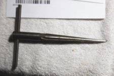
-Use a steel nail as a hole punch (just a dimpler in this case). It works really well and saves money.
-With the drill bit installed and tightened and the hand drill unplugged, hold the panel in the palm of your hand and the drill head secure in the other hand. Press the panel into the drill bit at the spot you've dimpled with the punch/nail and make many, many quarter turns until a bowl is shaven into the panel. It will take a long time, so hold the panel in a way that you won't warp or deform it.
-Once the concave cup is large enough for you to feel like you can use power without the head wandering, lube it up (place a few drops of oil, alcohol, water, spit, etc.) and get ready to be dangerous.
- Make sure the panel is completely dust and debree free and cover most of it in plastic (saran) wrap (don't covor where you're drilling). Place it on an equally clean, flat, and dust-free piece of wood you don't mind destroying. Place a second piece of clean wood on top of the part of the panel that is not being drilled. Kneel or step on that upper wood block, thus sandwiching everything. This will keep it secure, and also gives you the standoff you need incase it does turn into a spinning blade. It will only hit wood, and not your body, though it may damage the panel if that occurs. You could use a shoe instead of the upper block of wood if you don't mind that the panel may whack the side of that shoe at some point.
-Go easy on the drill. I like to have the drill handle glide against my leg (when I'm kneeling) so that if it catches, the torque doesn't hurt my wrist because the drill has to move against my leg as well.
Many cordless drills have brakes so they make it easy to rub the start of a hole. I think you'll be surprised at how tough aluminum can be to work with. If I were to do this, I'd have to get different drill bits. I have these gnarly bits that make wood seem like butter and are actually designed to go through cast iron (which they do quite nicely... but it takes a while). They catch thin metal very abruptly and I would absolutely have a problem with this panel once I first made it through to the other side. I also have two bits for porcelain, but nothing for aluminum that would leave a clean hole. I'd have to go pick up some traditional twist bits.
A step drill bit is great on a press, very good for thin materials like this panel, but I don't think it's very controllable by hand, though it may feel like it is. As it enlarges to a new step it "wobbles" because it moves into the new cut area... wandering from center a little with each new enlargement.
Is there a drill template in pdf format for the taller case ?
I can email you the FPD file for it if you send me your email addy in a PM
Whenever I drill a panel I always screw it to a piece of 2x4, that hold it nicely.
Can't believe I've never thought of that before, but what a great idea! Thanks for sharing.
Whenever I drill a panel I always screw it to a piece of 2x4, that hold it nicely.
Oh yeah... these panels have screw holes. I wouldn't lock them down with screw-head overlap because of cosmetic threats, but since these have screw holes... that makes this much easiler.
Good call.
Oh yeah... these panels have screw holes. I wouldn't lock them down with screw-head overlap because of cosmetic threats, but since these have screw holes... that makes this much easiler.
Good call.
Mask the holes with making tape, use wood screw with conical heads to minimize contact with the panel but still hold securely
Make sure your power switch is on. You won't get a voltage drop across D1 unless there is some current going through it. Does your LED still light when the power switch is turned on? Since the voltage drop across D1 will be that 0.16V - or - so make sure your DMM is on a low range, if manual, like 2V and on DC volts.
0.16V is OK for D1 on the diode test mode since it is a Schottky. Try measuring between ground and D5's cathode, see if you are getting around -12V. Then measure the voltage drop across D5.
Thanks agdr for your help. That makes sense, once I closed the circuit I got the expected voltage across D1. Every thing works now. I've also build an altoid cmoy over the weekend and the experience I got building the O2 made the much less documented CMOY an easier experience.
@RS the revised testing section and troubleshooting was very helpful. The pictures that showed the measurements for the different components I think was the most valuable to me. Thanks again for all your efforts and excellent documentation.
I almost finished another O2 with the remote pot/LED and 1/4" jack. It passed all the initial tests, but when I tried to listen there was way too much gain and as I fiddled with the pot it made all kind of noises before one of the pins snapped off. So I'll be replacing the pot soon. I gotta say the remote pot was the hardest to solder.
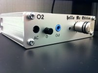
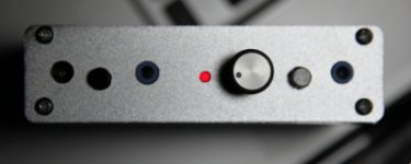
Her is the finished one. A thing of beauty
")
Attachments
@hbarradh, did you rob the CMoy of its knob or did you just get two? I do like the standard knob that JDS Labs employs.
I order a couple from digikey. I've also got one of the wider ones for the 1/4" version. It looks really nice with the black B30 box.
Tried 1x gain today (removed the grounding resistor). With 2.1V source both my (absolutely different, but low-impedance) headphones are still WAY too loud on high volume positions. I hope you, guys, are not listening to that kind of volumes on a daily basis.
I have also found a formidable opponent for O2 - soviet orthodynamic TDS-5M, copy of ancient Yamaha PH-1. Those are 100 Ohm (I measured 78 with DMM), but seem to have extremely low sensitivity. They also got sufficiently loud at 1X, but there was absolutely no margin, so higher gain was really necessary. Also, it is only with these phones that I have felt MOSFETs are getting even hotter while listening to music, compared to silence
I have also found a formidable opponent for O2 - soviet orthodynamic TDS-5M, copy of ancient Yamaha PH-1. Those are 100 Ohm (I measured 78 with DMM), but seem to have extremely low sensitivity. They also got sufficiently loud at 1X, but there was absolutely no margin, so higher gain was really necessary. Also, it is only with these phones that I have felt MOSFETs are getting even hotter while listening to music, compared to silence
Plastic washers'll do just fine too.Mask the holes with making tape, use wood screw with conical heads to minimize contact with the panel but still hold securely
Thanks hbarradah, glad you got everything working and it looks great! I should have added the trouble-shooting section a long time ago but I've been focused on other things.@RS the revised testing section and troubleshooting was very helpful. The pictures that showed the measurements for the different components I think was the most valuable to me. Thanks again for all your efforts and excellent documentation.
I should have added the trouble-shooting section a long time ago but I've been focused on other things.
Yeah, geez! Could you please drop everything you're doing and spend more time helping us for free? You're so selfish.
Awesome job with all you've done. Thank you!
More tips on drilling the front panel
Got a few tips on drilling the front panel. I printed out the front panel label adjusted to exactly fit the panel. Cut it out and taped one edge of panel printout and aligned it to the panel and hinged it open. Then I got some double sided scotch tape and laid three rows down on the top of the panel and folded the label back over the top of the panel. Got it right the first time. (The label has cross hairs at the center of each hole position.) Then I used an auto-centerpunch to dimple the center of each hole position. A hammer and nail or regular center punch just doesn't work for me. I always seem to lift the punch and end up with the dimple off center. I had some scrap plywood that was much bigger than the front panel, so I screwed the panel down to the plywood with the screws that came with the enclosure. Now I drilled out the holes with an 1/8th inch bit for the LED and a 1/4th inch bit for all the other holes.The paper/tape kept the burrs to a minimum on the top and the wood did the same for the back side. Now take a long thin reamer and use it to de-burr and enlarge the holes as necessary. I used a hand drill with some titanium-oxide coated drill bits.
Next I intend to gin up a front panel label and print it on glossy photo paper and spay the label with fixative and I'll an OK front panel.
Attachments
@rs and agdr: finally had a chance to reply. I ran it for a while and checked it a few more times and it seems to be fine now. Thanks for the troubleshooting and help. This was basically my first time using a soldering iron, so I'm glad I only made this one mistake. R12 looked fine, but I decided to reheat the solder and added a bit more too since both of you were pointing to it as a possible problem area.
The amp is working great and sounds great too. Thanks for the help!
Sent from my Transformer TF101 using Tapatalk
The amp is working great and sounds great too. Thanks for the help!
Sent from my Transformer TF101 using Tapatalk
Yeah, geez! Could you please drop everything you're doing and spend more time helping us for free? You're so selfish.
LOL!
- Home
- Amplifiers
- Headphone Systems
- The Objective2 (O2) Headphone Amp DIY Project