@Limp, did you run all the power controller tests in the Initial DIY Testing section? You might have static zapped a MOSFET and one of them is stuck on which would cause one rail to turn on before the other making for a much bigger transient. With either rail low, both MOSFETs should shut off. Be sure and conduct the tests with no headphones connected.
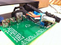
Remote mounting pot
I'm planning on running this using the batteries for most of the time. Puting the battery on the board, the wires are pretty much right on top of the batteries, may be 1mm over it. Is that ok? or will the batteries introduce noise into the pot cables?
I'm planning on running this using the batteries for most of the time. Puting the battery on the board, the wires are pretty much right on top of the batteries, may be 1mm over it. Is that ok? or will the batteries introduce noise into the pot cables?
Attachments
I'm getting 24V across C8 and C9.
Bugger, I guess that means being careful with those MOSFETs just isn't careful enough.
Bugger, I guess that means being careful with those MOSFETs just isn't careful enough.
Last edited:
@Limp, did you run all the power controller tests in the Initial DIY Testing section? You might have static zapped a MOSFET and one of them is stuck on which would cause one rail to turn on before the other making for a much bigger transient. With either rail low, both MOSFETs should shut off. Be sure and conduct the tests with no headphones connected.
Everything seems fine, right up to the Low Voltage Shutdown test. With one battery intalled I get ~.5V, and with the other I get about half that. Now both are below the .7V you mention in the blog, but it is still a prety large discrepancy.
Is this where the problem is?
I'm planning on running this using the batteries for most of the time. Puting the battery on the board, the wires are pretty much right on top of the batteries, may be 1mm over it. Is that ok? or will the batteries introduce noise into the pot cables?
unlikely, its DC, it doesnt introduce much EMI like transformers (AC) do.
Thank you very much for taking time to reply and educate me (I'm just starting to understand electronics).FIY, "decoupling capacitors" are used on power supply lines to decouple power supply noise from other components and present a low power supply impedance to components.
I feel severe lack of electrical engineering vocabulary. In Russian C13 and C14 would be called "decoupling" or "separating" caps as they decouple signal from DC component, and C17/C18 would be just called "filtering" caps.
Is there any site or book which could help me to quickly learn most common English terms of electrical engineering domain?
P. S.
Limp, thanks for the refernce photo!
Last edited:
unlikely, its DC, it doesnt introduce much EMI like transformers (AC) do.
cool, thanks qusp.
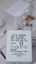
I am having a nightmare trying to find a power supplier for the O2 here in the UK. I have found this, would it work for the UK?
It will if the plug fits properly in the O2. The output ratings are fine. 16VAC 700mA puts it right between the WAU16-400 and WAU16-1000 adapters on the BOM in terms of current capability, but the manufacturer doesn't specify if the output plug is a 2.1mm.
Sandan Limited (BS)
If you have access to the adaptor just try it to see if it fits, otherwise maybe the seller could confirm what output plug it has.
Thanks for the info. I am not too worried about the output plug, that can easily be sorted out. I will get one and see how it goes as it is not so expensive.
Thanks again
Thanks for the info. I am not too worried about the output plug, that can easily be sorted out. I will get one and see how it goes as it is not so expensive.
Thanks again
Yep, you can always just cut the plug off and put on a 2.1mm if needed.
I'm getting 24V across C8 and C9.
Bugger, I guess that means being careful with those MOSFETs just isn't careful enough.
Just curious - which mosfets from those listed on the BOM did you use (which part numbers)?
interest in walkthrough?
Some days ago I announced that I would write a step-by-step walkthrough for the construction of the O2. Problem is, I got sick and now I have some catching up to do with other things. Given the lukewarm response to my initial announcement, I am now in doubt if I should continue making the walkthrough or not. If there's sufficient interest in it, I will finish it in a while, if not, I will simply abandon my current effort and move on to other things. Just let me know.
Some days ago I announced that I would write a step-by-step walkthrough for the construction of the O2. Problem is, I got sick and now I have some catching up to do with other things. Given the lukewarm response to my initial announcement, I am now in doubt if I should continue making the walkthrough or not. If there's sufficient interest in it, I will finish it in a while, if not, I will simply abandon my current effort and move on to other things. Just let me know.
I am having a nightmare trying to find a power supplier for the O2 here in the UK. I have found this, would it work for the UK?
Oslpag, I'm using this ac-ac multi-voltage adaptor from Maplin [it's the one listed in the BOM], measures just over 17v unloaded when set to 15vac out.
Paul
Oslpag, I'm using this ac-ac multi-voltage adaptor from Maplin [it's the one listed in the BOM], measures just over 17v unloaded when set to 15vac out.
Paul
Thanks Paul, don't know how I missed that one?
Just curious - which mosfets from those listed on the BOM did you use (which part numbers)?
FQU17P06 for Pch and the Nch says FQPF10N20C. It's what was supplied with Jokeners kit.
I have now replaced both MOSFETs and all tests seem ok. I get ~250mV on the Low Voltage Shutdown test, but there is still very loud 'pop' when I turn it on.
Last edited:
Some days ago I announced that I would write a step-by-step walkthrough for the construction of the O2. Problem is, I got sick and now I have some catching up to do with other things. Given the lukewarm response to my initial announcement, I am now in doubt if I should continue making the walkthrough or not. If there's sufficient interest in it, I will finish it in a while, if not, I will simply abandon my current effort and move on to other things. Just let me know.
I for one would be delighted by such a guide. I expect there are others but my feeling is that the majority may be lurkers unwilling to post. If you do decide to abandon it, would you instead consider a testing guide? Perhaps as a youtube video.
Yes I do it very often, lock the direction of rotation against a solid block, or if I'm making something like this the end panels are small and get too hot to hold
I screw the end panels onto the case and hold the body of the case while I drill works a treat 🙂
cheers
Great, thanks for that, Fredthedog. The Front Panel Express software has a print option that seems to work, to help us get the holes correctly positioned; although I had to modify the 'scale' option in the print dialog to 106.90% to get a perfect match.
FQU17P06 for Pch and the Nch says FQPF10N20C. It's what was supplied with Jokeners kit.
I have now replaced both MOSFETs and all tests seem ok. I get ~250mV on the Low Voltage Shutdown test, but there is still very loud 'pop' when I turn it on.
Thanks! Just curious about those. No ideas about the turn on pop though, unfortunately.
Anyone got any ideas on stenciling the markings on to a diy front panel? I'm currently thinking of using a common plastic stencil with a water based pen and then covering it with shellac or laquer. I did think of permanent marker but supposedly the alcohol in the shellac would make it smear. I'm also finding that permanent marker doesn't show up too well. I suspect water-based pen will be just as bad. Perhaps acrylic paint will be necessary.
- Home
- Amplifiers
- Headphone Systems
- The Objective2 (O2) Headphone Amp DIY Project