hey hey thar agdr =) lol 0.2mm? wow. yeah mostly even fine smd stuff i use pretty large tips, faster to bridge the whole lot and clean after than worry about bridging pins one at a time =) i guess you gotta be pretty confident in your abilities to set out to bridge all of the pins together as quickly and completely as possible =) but flux and soldermask is your friend, surface tension is definitely one of my favourite natural forces. confidence is more than half the battle. for pth the 1 or 2mm and occasionally the standard conical hakko tip
i just noticed i typed the above wrong too. i meant to say
i just noticed i typed the above wrong too. i meant to say
but you answered the question anyway, so all good.stuff that, get a second cheapie iron (not meter) and use both
Yes . . . well . . . since the O2 does drive HD650's without overheating the regulators when built to spec and functioning properly, there is clearly something wrong. It takes a substantial current drain to overheat (or fail) the regulators, and that current must be going someplace (that it doesn't in the spec build). Others have suggested that you post pictures . . . that might help . . . at very least please post the voltages you measure at the regulator inputs, regulator outputs, and on the supply buss (after the power management circuit).in my experience with two amps the O2 can't drive HD650's and not eventually overheat the regs to the point they suffer reduced performance or even fail. Maybe I did build both my amps wrong
Also, if the regulators are getting hot (and their outputs are not shorted to ground) then something else must be getting hot also (the power has to be dissipated somewhere) . . . there are not a lot of candidate locations, so it should be easy to find. Check particularly the MOSFETs (which should not get even warm) and any electrolytic caps (which if installed backwards can draw a lot of current . . . since they're relatively big it often takes a while for them to heat up, so leave it "on" for a bit).
For the regulator to heat up it has to be passing current, so you should look for a failure on the load side . . . either a short to ground or some other component that is also getting hot.uncontrolled heat up of U6.
When my O2 was functioning it had no issues driving the HD650 either. I noticed no parts heating up beyond normal operation. It drove both the HD650 and the 32ohm A-T headphone I have surprising well. I am using the stock build from BOM on RocketScientist's blog.
I initially thought that both U6 and U5 were heating up but after a complete shutdown and full cooldown I found that it was just U6. U5 felt hot just from the proximity of the two regulators. One was heat soaking the other.
I'll check my board tonight or this weekend for any shorts or solder breaks then try the suggestions that RocketScientist posted earlier.
Last edited:
Just to throw in one other piece of information here. There's no measurable change in the O2's performance from stone cold turn on compared to after it's been cranking hard into much more difficult loads than the 300 ohm HD650 (headphones I own and use with my O2 often) for hours. It takes the op amps a few seconds to settle down to their ideal internal bias points, and after that it makes no difference.
If the performance of 78xx and 78xx regulators significantly changed between 20C and 50C die temperature (well shy of their 125C max rating) I'm sure it would be well documented in the datasheets and elsewhere by now. They've been around forever, are made by at least a half dozen companies, and have been used by the millions. They're not even remotely some esoteric, or fussy, component.
If cheapskate's regulators are too hot to briefly touch driving HD650's (especially with no batteries installed), then either the AC wall transformer is putting out too much voltage, or as others have suggested, something else is drawing excessive current in the amp. It could be a wiring error, a wrong component, the amp could be oscillating at ultrasonic frequencies due to some error or mod, etc.
There have been several requests here and elsewhere for pictures of Cheapskate's amp detailed enough to show the components, op amps, etc. Such pictures would be very useful and helpful to trouble shoot this problem. As would the voltage measurements I have suggested.
Last edited:
OK, first of all, I want to stress this likely is NOT the problem being reported with near 0 volts on the negative rail and regulators failing. This also doesn't explain any 7812 problems. But it is a possibility that's worthy of further investigation if possible.
Agdr brought to my attention there are differences between datasheets for different brands of the 79xx regulator. I've reviewed 5 different datasheets and several of them are rather vague on the output capacitor requirements including On Semi. Fairchild has footnotes that don't seem to be referenced to anything, some suggest the capacitor is entirely optional, some "recommend" it, and one company (National) says it's "required". The rub is they suggest 1 uF not the 0.22 uF used in the O2. With the 7812 (positive regulator) the cap is genuinely optional for all brands.
I was trying to minimize the unique parts count for the O2 for a variety of reasons and that's why I used the same 0.22 uF film caps for C6 and C7 as used elsewhere in the amp. Under the assumption the caps are optional, that's a valid design choice. But I wasn't aware National requires a 1 uF cap. It's unlikely the 7912 is oscillating due to a 0.22 uF cap rather than a 1 uF cap but it's possible. For one thing, On Semi suggests caps are only needed with higher current requirements. And the the O2 typically runs well under 0.04 amps and it's a 1 amp regulator. That's only 4% of the regulator's current capability.
Well after I designed and tested the power supply, using NJR, Fairchild, and On Semi regulators, I added a 1 uF cap (C1) to improve the power on/off behavior. In hindsight, I should have specified that same cap for C6 and C7 just to be conservative. The original amp didn't have any 1 uF caps hence 0.22 uF made more sense.
National suggests a 1 uF tantalum or 25 uF electrolyic cap but I suspect that's related to the early days of the 79XX (it's a 2001 datasheet) before reasonably priced ceramic MLC caps even existed. So a 1 uF ceramic MLC should also work. If anyone knows differently, please let me know?
A REQUEST: For the two of you here who may be experiencing regulator problems, if you happen to have a spare 1 uF >= 16 volt ceramic cap (such as C1 used in the O2) or a 22 uF - 100 uF >= 16 volt electrolytic laying around, can you please carefully "tack solder" it across the outer two pins of U6 (the 7912) with short leads on the bottom side of your O2 board. Observe proper polarity if it's an electrolytic with the negative side on the regulator output pin. If your 7912 is genuinely dead, obviously it needs to be replaced first and any other problems corrected.
Because all my O2's, with three different brands of regulators, work perfectly I can't determine if the 0.22 uF cap could be a problem or not. If it's a problem it appears to be a very isolated problem as only 4 or so have reported any problems.
Last edited:
@dirkwright, Great! You're welcome!
#H3nk, it's not a big deal as long as the bottom solder connections look good (shiny, good "flow", etc.). If you plan on removing and installing batteries often you might want to add solder to the top of the battery terminals as mentioned in Circuit Board Construction to add some mechanical strength to the terminals. Electrically they're fine without it.
#H3nk, it's not a big deal as long as the bottom solder connections look good (shiny, good "flow", etc.). If you plan on removing and installing batteries often you might want to add solder to the top of the battery terminals as mentioned in Circuit Board Construction to add some mechanical strength to the terminals. Electrically they're fine without it.
The bottom joints looks good so it seems I have nothing to worry about. Terminals are fine as well I think. Thanks!#H3nk, it's not a big deal as long as the bottom solder connections look good (shiny, good "flow", etc.). If you plan on removing and installing batteries often you might want to add solder to the top of the battery terminals as mentioned in Circuit Board Construction to add some mechanical strength to the terminals. Electrically they're fine without it.
I have an issue after doing the initial tests. Everything was fine up to the moment I plugged in the "sacrificial" headphones. I heard some decent pops while plugging the phones in and out. Suddenly the red LED went off and one of the 4556ad exploded and has a hole on top now.
Now - without the opa's (the U2 seems to be functional due to DC tests) the LED stays off. I can measure the raw DC voltages but thats it. The O2 is dead.
What could I try?
Now - without the opa's (the U2 seems to be functional due to DC tests) the LED stays off. I can measure the raw DC voltages but thats it. The O2 is dead.
What could I try?
I just have some comments about the discussions of DMMs a few pages ago.
True RMS DMMs are of course the best, showing the true RMS voltage for most waveforms within specified frequency range. Remember this is often only up to a few kHz or less.
Some (most?) "Semi-cheap" multimeters often used the rectified average AC voltage (measured after a input cap to remove the DC component) usinga OP-based precision rectifier. The average voltage is then multipled a with 1.11 to calculate the RMS voltage. 1.11 is the ratio between the RMS voltage and the rectified average for a sinus wave. This means that these DMMs are good only for clean sine-waves at one frequency. They will show wrong values for all other waveforms, except pure sine waves. You can easily test this by applying a squarewave with 1V amplitude at a low frequency 50-100HZ to the DMM. For a square wave the RMS voltage equals the average voltage, and hence the multimeter will show ~1.11V if it is of the averaging type. The measured voltage could be one or a few hundreds of a volt lower due to that the normally low bandwidth of these DMMs cuts out some of the harmonics of the square wave from the measured voltage.
I have also investigated several "dirt cheap" DMMs (~10-15$) of different types. If you measure a pure DC voltage with these, in one polarity they will show 0V as expected, in the other direction the one Ishow 20V(!). I haven't checked the actual PCB, but to me this means two things. First the input DC-block capacitance is omitted. Second, the multimeter uses only one diode to make a half wave rectification, measures the average and multiplies with ~2.22. I do not think they even take care of the voltage drop of the diode if looking at the numbers carefully. For the main use of these multimeters it does not matter very much. (i.e., measuring if 12V or 6VDC is properly connected in cars, boats, bikes.... and measuring if 230V is connected at home). However, I would be very reluctant to trust these for measuring any low voltage AC-signals, especially non-pure-sines or with a DC level. I showed this to some students at a lecture and the very quite amazed. Somehow, you will get what you pay for.
I have an issue after doing the initial tests. Everything was fine up to the moment I plugged in the "sacrificial" headphones. I heard some decent pops while plugging the phones in and out. Suddenly the red LED went off and one of the 4556ad exploded and has a hole on top now.
Now - without the opa's (the U2 seems to be functional due to DC tests) the LED stays off. I can measure the raw DC voltages but thats it. The O2 is dead.
What could I try?
Post photos first.. so another set of eyes may notice what caused the problem..
+1 for MrSlim's suggestion. I suspect there was lots of DC voltage on the output if you heard a loud pop from the headphones. So you might not have made the DC measurements correctly before plugging the headphones in. Lots of different things can cause DC on the output.
First verify the voltages again per Initial Testing with the 3 audio op amps removed.
If that's OK, install U1 and the op amp that didn't fail in the same socket it was in before (leave the failed 4556 socket empty). Re-check the DC measurements. If they're OK, try the headphones again and see if at least one channel works OK and plays music. If so you've at least narrowed the problem down to being in just one channel and it's likely a solder bridge or poor connection, the wrong part installed somewhere, something in backwards, etc. Detailed photos would be a big help.
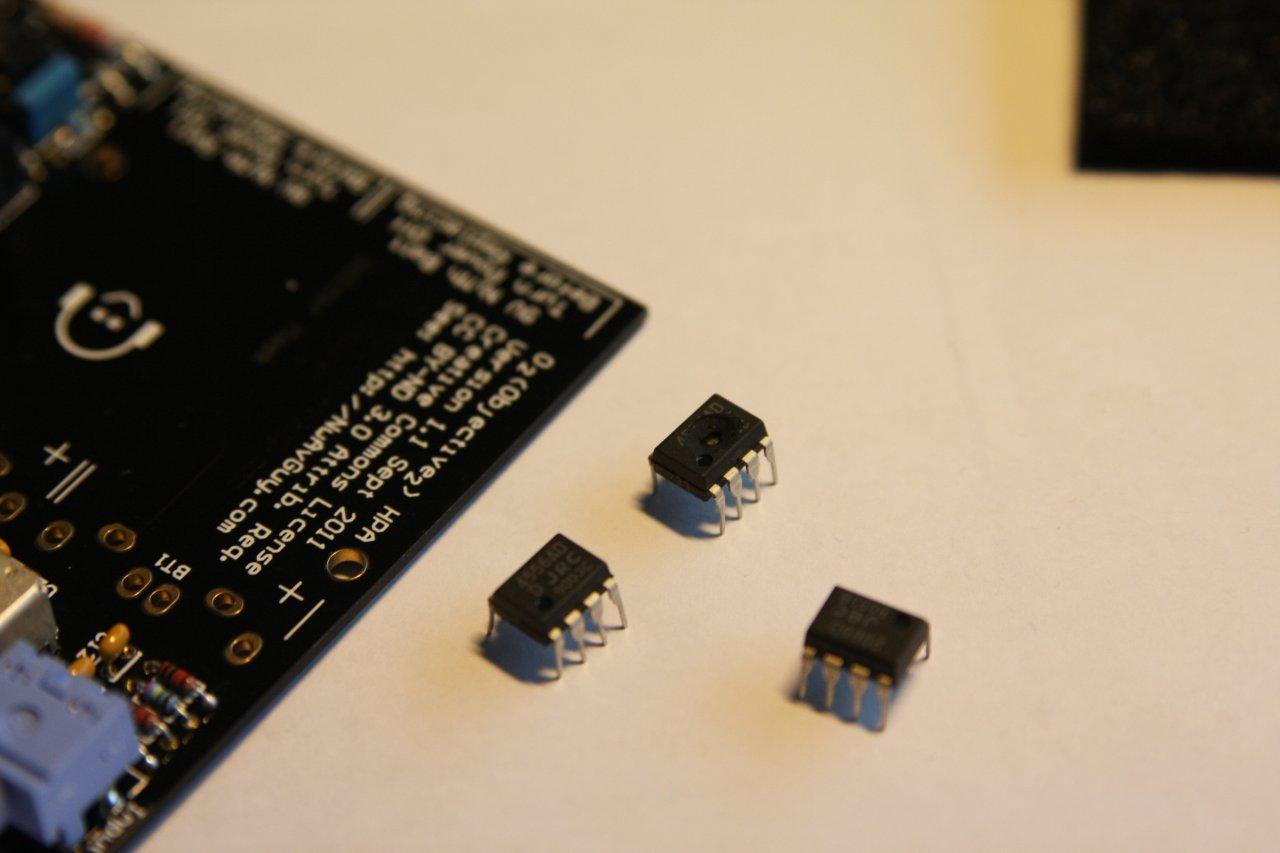
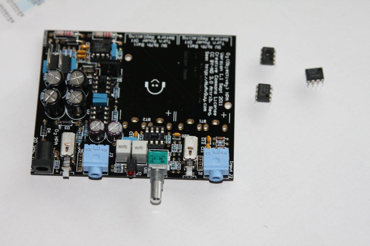
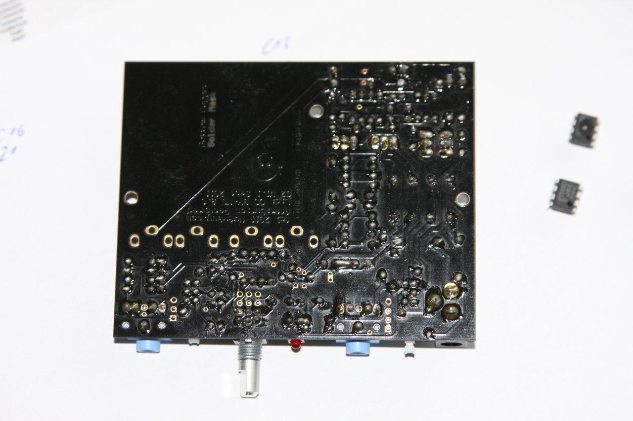
okay here are some photos ... the 3 audio amps removed. I will do some initial testing later this weekend. Since the LED stays off its not very promising to see anything on the output.Post photos first.. so another set of eyes may notice what caused the problem..

A REQUEST: For the two of you here who may be experiencing regulator problems, if you happen to have a spare 1 uF >= 16 volt ceramic cap (such as C1 used in the O2) or a 22 uF - 100 uF >= 16 volt electrolytic laying around, can you please carefully "tack solder" it across the outer two pins of U6 (the 7912) with short leads on the bottom side of your O2 board. Observe proper polarity if it's an electrolytic with the negative side on the regulator output pin. If your 7912 is genuinely dead, obviously it needs to be replaced first and any other problems corrected.
Because all my O2's, with three different brands of regulators, work perfectly I can't determine if the 0.22 uF cap could be a problem or not. If it's a problem it appears to be a very isolated problem as only 4 or so have reported any problems.
I put an order in a couple days ago for some tantalum .33uf caps and ceramic .1uf caps, I'll post my results.
Nothing else in either of my amps seems to even get warm to the touch.
I put an order in a couple days ago for some tantalum .33uf caps and ceramic .1uf caps, I'll post my results.
Nothing else in either of my amps seems to even get warm to the touch.
you really need to take some pictures of your o2
i've seen your posts in here and hf and you always dodge those requests. don't you have any camera?
okay here are some photos ... the 3 audio amps removed. I will do some initial testing later this weekend. Since the LED stays off its not very promising to see anything on the output.
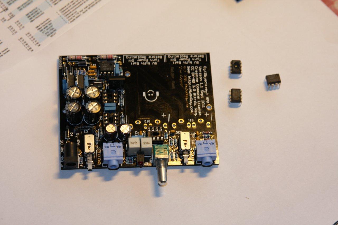

Looks like Q1 and Q2 might be installed backwards...
- Home
- Amplifiers
- Headphone Systems
- The Objective2 (O2) Headphone Amp DIY Project