Hi, all, First-time DIYer here. I have two questions I'm hoping you'll entertain. First, regarding the transformer: given the two transformers below and the default option on the BOM, which would be the appropriate choice when I'll be driving orthodynamic headphones (50 ohm) and low-impedance dynamic headphones? (Is there any reason for me to upgrade?)
What is the make and model of the two headphones... just to look up power handing and sensitivity? At 50mW per channel into 50 ohms that would be around 32mA per channel. Most likely the 16VAC 400mA transformer, but you might want to wait until RocketScientist logs in again to give you the best answer. Entirely possible that I'm missing something.
")
I just did this to help someone at head-fi, and I also got 200mV with only one battery in. Both batteries in I get 3mV.
Ok, this test needs to be done with headphones in, I'll have to recheck tomorrow...
Hey guys,
So NwAvGuy confirmed that the measurements are within normal specs. He has updated the DIY Initial Testing section to clarify. I just wanted to pass this information along for anyone in the same boat as me.
Thanks to all who've responded. Time to get back to listening to this amp worry-free.
Good luck to everyone on their builds.
Has anyone else had problems with the gain switch? I built two O2's the other day. One of them works fine, but the other doesn't work in high gain mode. I checked and rechecked and reflowed the solder joints. The only thing I can think that it might be is the switch, or a bad trace on the board. Is there anything else it could be?
I'm also having a different problem with both the amplifiers I built. I get an audible amount of crosstalk with both amplifiers, on both gain settings. When I play a signal through one channel, the signal is audible in the other channel, and gets louder when I increase the volume. Could this also be a problem with the gain switch? Could I have overheated the gain switches when I soldered and created the crosstalk problem?
Thanks to everyone for their suggestions, I appreciate your help.
Has anyone else had problems with the gain switch? I built two O2's the other day. One of them works fine, but the other doesn't work in high gain mode. I checked and rechecked and reflowed the solder joints. The only thing I can think that it might be is the switch, or a bad trace on the board. Is there anything else it could be?
I'm also having a different problem with both the amplifiers I built. I get an audible amount of crosstalk with both amplifiers, on both gain settings. When I play a signal through one channel, the signal is audible in the other channel, and gets louder when I increase the volume. Could this also be a problem with the gain switch? Could I have overheated the gain switches when I soldered and created the crosstalk problem?
Thanks to everyone for their suggestions, I appreciate your help.
pull the switch off the board and test it with a multimeter, check to make sure you have proper continuity for the switch position, and make sure that you haven't melted any contacts together (though this is probably unlikely, still worth checking).
also check your board for solder that may be bridging two points that should not be connected.
check to make sure you haven't melted anything in the input or output jack that would make the two channels connect.
I'm also having a different problem with both the amplifiers I built. I get an audible amount of crosstalk with both amplifiers, on both gain settings. When I play a signal through one channel, the signal is audible in the other channel, and gets louder when I increase the volume. Could this also be a problem with the gain switch? Could I have overheated the gain switches when I soldered and created the crosstalk problem?
Thanks to everyone for their suggestions, I appreciate your help.
As the gain stage is in front of the potentiometer, I'd say the two issues aren't directly connected.
Thanks for your replies, I appreciate your help and suggestions.
The gain switch problem seems to have been a poorly soldered switch. I must have been too concerned about overheating the switch, so I under heated it. I began desoldering it to remove it, and once I saw how difficult that would be, I decided to resolder it. I then reflowed all the pads on the whole board, and the problem went away.
As far as the crosstalk goes, perhaps I am seeing a problem where there isn't one. I have to turn the volume up fairly loud, and I suspect that I wouldn't be able to hear the crosstalk if both channels were playing.
So far so good, I think this is a good sounding amplifier. I still have to put it through the paces, but it definitely drives my Fostex T50RP's better than my Mini3.
-Aaron.
I'm also having a different problem with both the amplifiers I built. I get an audible amount of crosstalk with both amplifiers, on both gain settings. When I play a signal through one channel, the signal is audible in the other channel, and gets louder when I increase the volume. Could this also be a problem with the gain switch? Could I have overheated the gain switches when I soldered and created the crosstalk problem?
Thanks to everyone for their suggestions, I appreciate your help.
If you want to try a couple of tests it would help you track the problem down. Using some mini hook clips like this to keep from shorting anything out in the process
Mini-Clip Jumper Wires - RadioShack.com
try shorting the side of R3 connected to the op amp (the side furthest from the board edge) to ground and see if the problem goes away. Then try the same with the op amp side of R7 (furthest side from board edge again). You can get ground at the middle pin "2" of the P1 connector.
You are just grounding the gain-stage inputs here. If the problem goes away then the internals of your input jack are shorted. If not then the problem is downstream, such as a bad U1, gain switch problem, a solder bridge between traces or a part in the wrong place.
Be sure to hook the clip onto the lead of the part first, with the amp power off, to keep from shorting anything. Then power it up and ground the other end of the lead and have a listen.
Hello, im making an order on mouser and these parts are backordered:
594-K221J15C0GH5TL2 - Multilayer Ceramic Capacitors (MLCC) - Leaded 220pF 100volts 5% C0G 2.5mm LS
270-2.74M-RC - Metal Film Resistors - Through Hole 2.74Mohms 1% 50PPM
270-165-RC - Metal Film Resistors - Through Hole 165ohms 1% 50PPM
270-243-RC - Metal Film Resistors - Through Hole 243ohms 1% 50PPM
Can you help me find some equivalent parts that are in stock somewhere please? Thanks!
Hello, im making an order on mouser and these parts are backordered:
594-K221J15C0GH5TL2 - Multilayer Ceramic Capacitors (MLCC) - Leaded 220pF 100volts 5% C0G 2.5mm LS
270-2.74M-RC - Metal Film Resistors - Through Hole 2.74Mohms 1% 50PPM
270-165-RC - Metal Film Resistors - Through Hole 165ohms 1% 50PPM
270-243-RC - Metal Film Resistors - Through Hole 243ohms 1% 50PPM
Can you help me find some equivalent parts that are in stock somewhere please? Thanks!
Newark has the Caps... they also have the B2/B3 cases.. so add to the same order. You might have to go up to 1/4 watt on the resistors though. Mouser doesn't seem to have any other 1/8 equivalents, and neither does Newark. Since they are physically larger, the 1/4w ones won't lie down nice like the 1/8's, (I had to replace one of those myself , can't remember which ones..) I haven't check to see if the lead size is too large for the holes .
Hello, im making an order on mouser and these parts are backordered:
594-K221J15C0GH5TL2 - Multilayer Ceramic Capacitors (MLCC) - Leaded 220pF 100volts 5% C0G 2.5mm LS
270-2.74M-RC - Metal Film Resistors - Through Hole 2.74Mohms 1% 50PPM
270-165-RC - Metal Film Resistors - Through Hole 165ohms 1% 50PPM
270-243-RC - Metal Film Resistors - Through Hole 243ohms 1% 50PPM
Can you help me find some equivalent parts that are in stock somewhere please? Thanks!
Here are some. These might not have been in stock when RocketScientist made up the BOM alternates -
For the 2.74M you can likely use a 2.70M
270-2.7M-RC Xicon Metal Film Resistors - Through Hole
That is a hysteresis resistor and should not be terribly critical, plus he already lists a 2.70M resistor as one of the alternates. But that is a 5% carbon resistor and this is a nice 1% metal film, the same series as the original 2.74M
The other two are just gain resistors so you can use values near to the originals for a slight change in gain ratio.
For the 165R you could use a 162R of the same series
270-162-RC Xicon Metal Film Resistors - Through Hole
again he lists a 162R as one of the alternates. This time that alternate is a very high quality resistor but is more expensive. Your gain ratio with the 165 would have been [1 + 1500/165] = 10.09. With the 162R it would be [1 + 1500/162] = 10.26.
For the 243R you could use a 240R of the same series
270-240-RC Xicon Metal Film Resistors - Through Hole
Your gain ratio with the 243R would have been [1 + 1500/243] = 7.17. With the 240R it would be [1 + 1500/240] = 7.25.
I just discovered the SIP sockets on the BOM for replaceable gain resistors are out of stock too at Mouser, the 535-10-0518-10. Any of the 535-XX-1058-10 series at Mouser would work and most of the rest are still in stock.
Mouser Electronics - Electronic Component Distributor IC & Component Sockets
The XX is just the number of pins. RocketScientist lists 8 as being needed, cut individually out of that strip of 10 in the BOM. So instead two of the 4 pin strips could be ordered to give 8
04-0518-10 Aries IC & Component Sockets
or 3 strips of 3
03-0518-10 Aries IC & Component Sockets
or 8 individual pins (saves cutting)
01-0518-10 Aries IC & Component Sockets
Got my amp all built using stock gains, x2.5 and x6. With my HD558s only one channel plays normal on the first gain x2.5 and on x6 both channels are balanced just fine. Not sure if that is something to do with the gains or if something went wrong with the build. Any suggestions as to what should check out?
Thanks
Thanks
Got my amp all built using stock gains, x2.5 and x6. With my HD558s only one channel plays normal on the first gain x2.5 and on x6 both channels are balanced just fine. Not sure if that is something to do with the gains or if something went wrong with the build. Any suggestions as to what should check out?
Thanks
Check around the gain switch and U1 for solder bridges to the PCB ground plane. The metal shell of the gain switch is connected to ground via the two pins at the corners and the two middle pins of the 6 gain switch pins are soldered to ground. You might have a bridge from one of the remaining 4 pins of the switch to one of those. A magnifying glass is highly recommended for this one! Some bridges can be very hard to see just by eye.
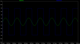
If the gain switch were just bad/open (no connection) you would get a gain of 1 in that position. Would still sound OK in that channel, just not as loud. But if the gain switch gets shorted to ground in one channel the inverting input of U1 gets grounded and effectively turns the op amp into a comparator.
Your incoming music waveform would get converted into square waves at the same frequency which would sound very distorted. Below is a plot of what happens there. You can also test for a solder bridge by unplugging the amp from the AC adaptor and pulling out the batteries to disconnect all power. Then measuring with an ohmmeter from pin 6 of U1 to ground (metal shell of the gain switch) and flip the gain switch in both positions. Then do the same with pin 2 of U1. If you measure a dead short to ground at either pin in one of the gain switch positions, there is your solder bridged trace.
The other thing to check is that the values of R17 match R21, and R19 matches R23, of course. With the amp powered down and disconnected as above you can just measure across those resistors with the ohmmeter. In one position of the gain switch you should get the right reading.
Good luck!
Attachments
- Home
- Amplifiers
- Headphone Systems
- The Objective2 (O2) Headphone Amp DIY Project