I made this based off of the untested version. Has text on it, and the panel is in black. The lettering is "natural", meaning no fill color. I’m going to send the file in to them and see about pricing.
Panel costs are as followed, per their program.
1 - $20.82
5 - 9 $18.74
10 - 19 $16.66
20 - 29 $14.57
Panel costs are as followed, per their program.
1 - $20.82
5 - 9 $18.74
10 - 19 $16.66
20 - 29 $14.57
An externally hosted image should be here but it was not working when we last tested it.
It has been suggested that a desktop version use a LM317/337 based supply, which would give adjustable voltages (up to the opamps' rated maximum of +/-18 V) that would be quieter to boot. Maximum output would increase to about 11 Vrms, giving some 3 dB more headroom. That should do, though it doesn't reach the impressive ~20 Vrms for Lake People / Violectric amps or even 32 Vrms for the SPL Phonitor / Auditor (all much fancier concepts, of course).
In fact most any self-respecting hi-fi (speaker) power amp is specified at the "knee". 1% THD is industry standard for portable devices.
I think +-18V PS with 11vrms out would be fine for the AKG 240's. Is it as simple as changing upping the transformer heatsinks/changing the LM reference resistors? Of course propably take a look at any passive compomemt votage ratings, but I can't think the amp section would need to change at all ?
Edit: I see there is some sort of opamp + mofset low noise series regulator after the Lm317/Lm337, probably would have to change biasing resistors to set it for a higher V out. Damn I hate spice. anyone worked this out yet or have a spice model they could share (this is open source right?)?
Last edited:
I think +-18V PS with 11vrms out would be fine for the AKG 240's. Is it as simple as changing upping the transformer heatsinks/changing the LM reference resistors? Of course propably take a look at any passive compomemt votage ratings, but I can't think the amp section would need to change at all ?
Edit: I see there is some sort of opamp + mofset low noise series regulator after the Lm317/Lm337, probably would have to change biasing resistors to set it for a higher V out. Damn I hate spice. anyone worked this out yet or have a spice model they could share (this is open source right?)?
This looks more like a comparitor killing supply if the voltage drops below 7V, looks like this shouldn;t be affected by a +-18V supply either.
I am going to try a desktop 36V O2 for these stubborn inefficient 600 ohm studio headphones, lot cheaper than building anything else I can think of.
regal: just wanted to make sure you knew that the "desktop version" is a different PCB that RocketScientist is working on that won't be available for awhile (months?). That one apparently won't have batteries.
If you bump the existing portable O2 rail voltage up to +/-18v with fixed regulators (LM7818, LM7918) you are probably OK as long as you are only using those higher impedance 600R cans. There is a power dissipation issue to watch there, of course, in the output NJM4556s vs. rail voltage and output load. The NJM4556's are 700mW total (for both amps in the chip) and the load is divided across the two of them. If it were me I would de-rate that to 500mW or so for the enclosed (chassis) ambient and parts proximity.
But - don't plug in any batteries! The existing charging circuit is just a resistor. It would try to charge the 8.4V cells to 18V and do it at a higher-than-specified charging current. You might want to not even solder in battery clips just so there is no mistake.
Last edited:
I've just spent two hours writing a boringly lengthy comment on flynhawaiian's design, going into great detail to show both its benefits and problems, proposing alternative approaches to overcome the problems, showing pictures to illustrate my points.
Well, consider yourself lucky: you won't have to read any of it. The internet ate my comment the moment I pressed "Submit Reply" and I won't write it all up again (yes, I had constantly CTRL+C'ed the text before each of the countless post previews, but at the very end I CTRL+V'ed another image URL into the text and forgot to CTRL+C the whole text one last time – learn from my mistake).
So please excuse the radically abridged style:
Benefits of flynhawaiian's design:
-provides useful information (like power supply requirements)
-attempts to solve text alignment problem arising from differently sized and irregularly placed holes by alternating label placement above/below
Problems of flynhawaiian's design:
-"Gain" label prone to be at least partly covered by volume knob; moving label down would create new (aesthetic) problems etc.
-attempts to overcome space constraints by employing extremely small text size (lowercase letters 1 mm high, line width 1.5 times the thickness of a human hair), resulting in some characters melting together (already on screen; probably worse engraved in aluminium) and overall bad expected readability (does some happen to have a picture of a panel with similarly small text?)
Improvements might be:
-increase text size
-shorten labels ("Gain High/Low" -> "Gain", "GN" or "G") and/or
-label only those elements that can be mistaken for each other (audio in/out jacks, power/gain switches)
Possible alternative might look like this (click to see):
-View image: 02front
-3.4 mm effective text size, 0.4 line width
-label placement problems solved by leaving out labels for self-explanatory elements (volume knob, power jack)
Last edited:
I think +-18V PS with 11vrms out would be fine for the AKG 240's..... anyone worked this out yet or have a spice model they could share (this is open source right?)?
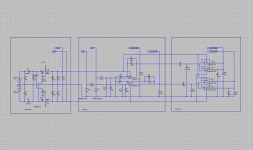
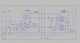
Here you go.

+/-18Vdc rail input voltage from the regulators.
600R loads with 100pF in parallel. Amp gain 6.5x, pot "set" at maximum.
15V zeners added between mosfet gate and rails to protect the mosfets.
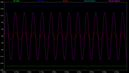
Simulation results +/-18v rails:
* maximum output voltage (onset of stage 2 clipping) = 9.7Vrms = 13.7Vpeak.
* the second stage clips just slightly before the first stage, which is good. Maximum output is limited by the second stage.
* With a gain of 6.5x the maximum input voltage at the onset of output clipping = 1.55Vrms = 2.2Vpeak, or with a gain of 2.5x: 4.0Vrms = 5.7Vpeak.
* RMS power to the load at onset of clipping is 156mW into 600 ohms, RMS current to the load is 16mA, and peak current to the load is 22.8mA.
* Voltage overhead in the NJM4556 chip at the onset of clipping = 3.9V. Power supply (diode, mosfet) overhead = 0.4V leaving 17.6V rails to the 2068 and 4556 chips.
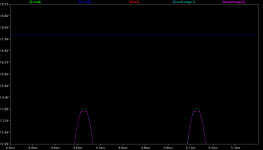
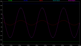
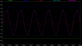
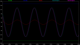
Labels are at the top of the plots, mouse over the plots for sim conditions in the title. Purple is the amp output (stage 2, the NJM4556s) while aqua is the output of stage 1 (the NJM2068s). Blue and green are the power supply rails at the chips and red is the input.
The second plot shows the very onset of stage 2 clipping at 13.7Vpeak at 2kHz. The 3rd and 4th plots are just closeups of the clipping. The next 2 plots are the same at 25kHz and 10Hz.
Attachments
-
 O2 18V rails circuit.png37.3 KB · Views: 149
 -
 O2 18V rails Vin=2.2Vrms start clipping 1 2kHz.png23.6 KB · Views: 151
 -
 O2 18V rails Vin=2.2Vrms start clipping 2 2kHz.png16.9 KB · Views: 108
 -
 O2 18V rails Vin=2.2Vrms start clipping 3 2kHz.png22.9 KB · Views: 112
 -
 O2 18V rails Vin=2.2Vrms start clipping 25khz.png24.6 KB · Views: 102
 -
 O2 18V rails Vin=2.2Vrms start clipping 10Hz.png25.5 KB · Views: 80
 -
 O2 18V rails circuit amp section.png35.2 KB · Views: 119
Last edited:
I had a go myself.
Will be a bit more expensive than jpgs due to multiple in-fill colours, but it is a just a proposal in case anyone want a panel for a silver case.
Will be a bit more expensive than jpgs due to multiple in-fill colours, but it is a just a proposal in case anyone want a panel for a silver case.
An externally hosted image should be here but it was not working when we last tested it.
Or a bit simpler:
This is too much fun!
How can we ever agree?
An externally hosted image should be here but it was not working when we last tested it.
This is too much fun!
How can we ever agree?
Sorry for the offtopic reply, but i think this could be of great use for everyone who have lost (or know that they will lose) all information like jpg did this time.
If you use firefox there are addons to save any text you type into a box automatically which protects you if the browser crashers, or if you just manage to close it before posting.
I'm using "Textarea Cache" at the moment, but i recently found "Lazarus: Form Recovery" which might be better at least for the people who prefer encrypted data.
https://addons.mozilla.org/en-US/firefox/addon/textarea-cache/
https://addons.mozilla.org/en-US/firefox/addon/lazarus-form-recovery/
+/-18V O2 should also work for 250R and up cans
Working through the NJM4556 chip maximum dissipation numbers, it appears that a +/- 18V rail modification on the O2 would support not only 600 ohm headphones, but impedances down to 250 ohms. The K240DFs that have been mentioned in the Head-Fi thread are 600 ohm and 200mW headphones. The 153mW maximum of the 18V version would be a good match, probably better than the 88mW maximum into 600R of the standard 12V O2 version.
The NJM4556 maximum dissipation with the +/-18V rails and the 600 ohm headphone load is the maximum total (RMS) input power to the chip minus the maximum load power: (17.6V)(16mA) - 156mW = 125.6mW. That is substantially under both the NJM4556 rated dissipation of 700mW and an ambient-derated guess of 500mW, so dissipation isn't a problem. With a 250 ohm headphone load the maximum NJM4556 dissipation goes up to around 307mW, still in bounds.
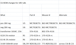
I've attached a BOM with the changes to make the O2 work with 18V rails for 250R - 600R headphones. Best to wait until RocketScientist weighs in before ordering anything though! I could easily be missing something about the 18V modification. But from what I can see in the simulation it would work just fine as long as only 250 ohm headphones or above are used and nothing lower impedance. Lower impedance cans could result in excess power dissipation in the output chips and likely too much current out to the cans.
Even at 250 ohms that is a maximum of 376mW to the cans with a maximum source and the volume all the way up, likely more power than they could handle. With 600 ohm headphones though that most likely isn't and issue.
Working through the NJM4556 chip maximum dissipation numbers, it appears that a +/- 18V rail modification on the O2 would support not only 600 ohm headphones, but impedances down to 250 ohms. The K240DFs that have been mentioned in the Head-Fi thread are 600 ohm and 200mW headphones. The 153mW maximum of the 18V version would be a good match, probably better than the 88mW maximum into 600R of the standard 12V O2 version.
The NJM4556 maximum dissipation with the +/-18V rails and the 600 ohm headphone load is the maximum total (RMS) input power to the chip minus the maximum load power: (17.6V)(16mA) - 156mW = 125.6mW. That is substantially under both the NJM4556 rated dissipation of 700mW and an ambient-derated guess of 500mW, so dissipation isn't a problem. With a 250 ohm headphone load the maximum NJM4556 dissipation goes up to around 307mW, still in bounds.
I've attached a BOM with the changes to make the O2 work with 18V rails for 250R - 600R headphones. Best to wait until RocketScientist weighs in before ordering anything though!
I could easily be missing something about the 18V modification. But from what I can see in the simulation it would work just fine as long as only 250 ohm headphones or above are used and nothing lower impedance. Lower impedance cans could result in excess power dissipation in the output chips and likely too much current out to the cans. Even at 250 ohms that is a maximum of 376mW to the cans with a maximum source and the volume all the way up, likely more power than they could handle. With 600 ohm headphones though that most likely isn't and issue.
Attachments
Last edited:
Flyhawaiian and others, if you can be patient until tomorrow, I am supposed to get my front panel in. Then the front panel cad, if needed, can be updated. I haven't done any fancy lettering or anything, but at least you would get an idea if NwAvGuy... er, RocketScientist's cad file works or not.
Working through the NJM4556 chip maximum dissipation numbers, it appears that a +/- 18V rail modification on the O2 would support not only 600 ohm headphones, but impedances down to 250 ohms. The K240DFs that have been mentioned in the Head-Fi thread are 600 ohm and 200mW headphones. The 153mW maximum of the 18V version would be a good match, probably better than the 88mW maximum into 600R of the standard 12V O2 version.
The NJM4556 maximum dissipation with the +/-18V rails and the 600 ohm headphone load is the maximum total (RMS) input power to the chip minus the maximum load power: (17.6V)(16mA) - 156mW = 125.6mW. That is substantially under both the NJM4556 rated dissipation of 700mW and an ambient-derated guess of 500mW, so dissipation isn't a problem. With a 250 ohm headphone load the maximum NJM4556 dissipation goes up to around 307mW, still in bounds.
I've attached a BOM with the changes to make the O2 work with 18V rails for 250R - 600R headphones. Best to wait until RocketScientist weighs in before ordering anything though!
Even at 250 ohms that is a maximum of 376mW to the cans with a maximum source and the volume all the way up, likely more power than they could handle. With 600 ohm headphones though that most likely isn't and issue.
I'm really surprised you're suggesting running the chips at their absolute max ratings when the datasheets, and general engineering practice, says not to. Running the O2 with 18 volt rails greatly increases the risk of an op amp failure that could take out your headphones with DC.
The tolerances on the regulators allow for them to be over 18 volts which would place even greater stress on the op amps. Also, the charging resistors for the batteries would have to be changed and the charge current would no longer significantly taper off at full charge.
If someone has the K240DF and they like to listen really loud and are sure that 7 Vrms isn't enough, they might want to consider switching to 15 volt regulators. But everyone else should stick with the 12 volt parts where the O2 will already hit 110 - 120+ dB SPL without clipping.
The main danger with higher rails is power dissipation. Even 15 volt rails increase the power dissipation by 1.5X and 18 volt rails increases it by 2.25X. Those are huge increases.
The 4556's, as documented in the O2 Circuit Description, is already within about 20% of its thermal limit playing music under worst case conditions. A 50% increase will easily put it over the limit. So the O2 would only be safe to use with very high impedance headphones. Accidentally plugging in lower impedance headphones could cause it to fail. This defeats the entire "one size fits all" approach for the amplifier.
Anyone is free to swap parts etc. But doing so without considering the consequences, like op amp failure, may put your headphones at risk. And, in this case, it's only trying to solve a "problem" that might not be a problem at all (some very rare headphones driven to very loud levels).
Last edited:
Flyhawaiian and others, if you can be patient until tomorrow, I am supposed to get my front panel in. Then the front panel cad, if needed, can be updated. I haven't done any fancy lettering or anything, but at least you would get an idea if NwAvGuy... er, RocketScientist's cad file works or not.
Awesome. Can't wait to get confirmation on that. It might be the first *real* front panel I do. Drilling those without a press drill is *really* delicate work.
How do you calculate DC offset created by R12 (R13)? You've measured 3 mV typical offset, but did you by any chance check with other BJT op amps? If one was silly enough to compensate this offset, how would one do that? Thanks in advance.
The DC offset is the input bias current multiplied by the value of R12. In all 4556 samples I've tried it's been under 4 mV.
There are no other BJT op amps that are a suitable replacement for the 4556 unless you're only using high impedance headphones. That's discussed in the Circuit Design and Circuit Description sections. There's more info in the Op Amps Measurements article.
Are you concerned the offset is too high, want to change the value of R12, or have some other concern?
- Home
- Amplifiers
- Headphone Systems
- The Objective2 (O2) Headphone Amp DIY Project