A normal XLR to RCA adapter will only use half the balanced output and the voltage drops to 2.1 V RMS. If you tried to tie the two "hot" balanced outputs to the RCA to get 4.2V, half the balanced output from each channel would be shorted to ground inside the amplifier.yeah but personally, i always use the balanced output using xlr-rca converter and feed it to my single ended amp since the balanced out sounds better than the single ended one
Likewise, I was just trying to give some guidance to the folks here who are unable to grasp basic math or comprehend the O2's superbly detailed documentation.
Joel and USG: Why point out to others how many volts your source puts out?
Line outputs that follow CD Redbook standard puts out 2V typical. Diff outputs are 4.5V typ.
If you are genuinely interested in the O2 as a DIY project, then it's up to you to set the output level of your source correctly or in lieu of being able to do so, then set the input gain of the O2 correctly.
Again, you've pointed out how your source might overdrive the O2 in default 3X gain. None of you have bothered to ask how to change the gain to 1X or 2X, or after reading this forum and the O2 docs stated that you will, I can only assume you do not possess sufficient skills to DIY this project.
Likewise, I was just trying to give some guidance to the folks here who are unable to grasp basic math or comprehend the O2's superbly detailed documentation.
Joel and USG: Why point out to others how many volts your source puts out?
Line outputs that follow CD Redbook standard puts out 2V typical. Diff outputs are 4.5V typ.
If you are genuinely interested in the O2 as a DIY project, then it's up to you to set the output level of your source correctly or in lieu of being able to do so, then set the input gain of the O2 correctly.
Again, you've pointed out how your source might overdrive the O2 in default 3X gain. None of you have bothered to ask how to change the gain to 1X or 2X, or after reading this forum and the O2 docs stated that you will, I can only assume you do not possess sufficient skills to DIY this project.
well, rocketscientist asked for input, i was just trying to give one..

personally i already quite understand and pretty much know what to do with my pcb when it shows up on my door
Last edited:
I just looked up my Stello DA100 and it has a 2.4Vrms output signal level. I've never thought of the Stello as being a "hot" source but it seems to be very close to the maximum with a 2.5 gain.
My Pico portable dac is listed as having an output of 2.84Vrms on the HeadAmp web site (maybe I'm reading it wrong). Link I never thought of the Pico as being a particularly "hot" source either and have plugged it into all my amps, both portable and desktop, with no problems.
My feeling is that there might be a few more 2+V sources out there then we realize, but I'll leave it to the EEs here to sort it out.
The Stello DA100 only outputs 1.2 Vrms. The Stello DA100 Signature is listed as 2.4 Vrms but it doesn't specifiy whether or not this is balanced output... do you know which it is?
The pico is a DAC+HPA, the 2.84 Vrms quoted is max output from the amp section. Turning down the volume on the pico would allow for less voltage here.
The amp was made to be useful for sources that don't have a preamp out. Like portable devices and such. These guys are on about something because they can't blowtorch the input with 4vp from a preamp that they could either remove from the signal chain altogether, or simply attenuate. The loudness of this amp, at the right gain setting, would not require you to overdrive the input with any set of phones I can think of.
Why this happens.
The volume control pot was placed between the gain and buffer stages of the amp for various reasons. One of them being the opamp that was chosen for the gain stage. Ultimately, the attenuation could be moved to its own stage with buffers flanking but that would require at least two extra dual opamps and more board space etc. They could blowtorch that attenuation stage all they wish. There are always trade offs. This amps claim is superior performance at reduced cost. Not that one can't overload the input with a ridiculous amount of signal.
Thanks, that makes sense. So, say I wanted to use a higher gain setting for 600 ohm headphones - All I would have to do is reduce the volume of the source? i.e. set my Music Streamer II to like 50% instead of the usual 100%?
I think I could live with that.

Last edited:
I just looked up my Stello DA100 and it has a 2.4Vrms output signal level. I've never thought of the Stello as being a "hot" source but it seems to be very close to the maximum with a 2.5 gain.
My Pico portable dac is listed as having an output of 2.84Vrms on the HeadAmp web site (maybe I'm reading it wrong). Link I never thought of the Pico as being a particularly "hot" source either and have plugged it into all my amps, both portable and desktop, with no problems.
My feeling is that there might be a few more 2+V sources out there then we realize, but I'll leave it to the EEs here to sort it out.
That is the Pico DAC/Amp you're linking to. If this is what you are going to use as a source there is no problem, as it has a pot for you to attenuate those 2.84Vrms.
I have the Pico DAC myself, and plan to use it with the O2. If I read the WM8740 specs correctly, and these are applicable for estimating analog outputs, it should only be about 2Vrms, tops, so no problem.
(please, anyone, correct me if I'm talking non-sense here)
<snip>
My Pico portable dac is listed as having an output of 2.84Vrms on the HeadAmp web site (maybe I'm reading it wrong). Link I never thought of the Pico as being a particularly "hot" source either and have plugged it into all my amps, both portable and desktop, with no problems.
<snip>
.
Correction: I think the2.84 figure is for the amp/dac
I'll put some thought into making the article more clear. But it's best to work backwards from your headphones something like this:Thanks, that makes sense. So, say I wanted to use a higher gain setting for 600 ohm headphones - All I would have to do is reduce the volume of the source? i.e. set my Music Streamer II to like 50% instead of the usual 100%? I think I could live with that.
Say you're going to use the Beyer DT880-600's which are the most voltage hungry cans I could come up with. They need about 5 V RMS to hit a seriously loud 110 dB SPL (the math is shown in the Gain Settings section).
Next you want to consider the source. The Music Streamer II specs list a "somewhat hot" 2.25 V RMS.
Then you figure out the gain: 5V Out / 2.25 V In = 2.2X to hit 110 dB SPL. So the default Low Gain setting of 2.5X will push the Beyer's past 110 dB at 0 dBFS.
You can also check for the maximum gain with the MS II if you want. For AC power that's 7/2.25 = 3.1X.
So if I was going to use the 600 ohm beyers with the MS II DAC, I'd aim for 2.5X - 3.0X and leave the DAC at full volume.
If you needed extra gain for something that was recorded/ripped way below normal levels, you could simply turn down the DAC volume, set the O2 to full volume, and use the 6.5X High Gain mode of the O2. Operated at max volume the output stage will clip before the input stage. Which means you get the full 7+ V RMS with no input clipping--plenty to ruin your hearing even with the voltage hungry 600 ohm Beyers.
To sum it up: Even using the default gains the O2 should work just fine with the 600 ohm Beyers and the HRT MS II DAC.
Last edited:
Likewise, I was just trying to give some guidance to the folks here who are unable to grasp basic math or comprehend the O2's superbly detailed documentation.
Joel and USG: Why point out to others how many volts your source puts out?
Line outputs that follow CD Redbook standard puts out 2V typical. Diff outputs are 4.5V typ.
If you are genuinely interested in the O2 as a DIY project, then it's up to you to set the output level of your source correctly or in lieu of being able to do so, then set the input gain of the O2 correctly.
Again, you've pointed out how your source might overdrive the O2 in default 3X gain. None of you have bothered to ask how to change the gain to 1X or 2X, or after reading this forum and the O2 docs stated that you will, I can only assume you do not possess sufficient skills to DIY this project.
LOL, my post was answering RS request for numbers just like joel's was.
I'll put some thought into making the article more clear. But it's best to work backwards from your headphones something like this:
Say you're going to use the Beyer DT880-600's which are the most voltage hungry cans I could come up with. They need about 5 V RMS to hit a seriously loud 110 dB SPL (the math is shown in the Gain Settings section).
Next you want to consider the source. The Music Streamer II specs list a "somewhat hot" 2.25 V RMS.
Then you figure out the gain: 5V Out / 2.25 V In = 2.2X to hit 110 dB SPL. So the default Low Gain setting of 2.5X will push the Beyer's past 110 dB at 0 dBFS.
You can also check for the maximum gain with the MS II if you want. For AC power that's 7/2.25 = 3.1X.
So if I was going to use the 600 ohm beyers with the MS II DAC, I'd aim for 2.5X - 3.0X and leave the DAC at full volume.
If you needed extra gain for something that was recorded/ripped way below normal levels, you could simply turn down the DAC volume, set the O2 to full volume, and use the 6.5X High Gain mode of the O2. Operated at max volume the output stage will clip before the input stage. Which means you get the full 7+ V RMS with no input clipping--plenty to ruin your hearing even with the voltage hungry 600 ohm Beyers.
To sum it up: Even using the default gains the O2 should work just fine with the 600 ohm Beyers and the HRT MS II DAC.
Awesome! And people say this is an issue. . .

OK, no more questions.
Can't wait building one. I'll definitely use 1x as low gain setting because I have sensitive headphones, sensitive ears and never understood the craze for more power than is ever going to be needed. What's the point. It's just a waste of volume control range and, with designs where it is in front of the gain stage, adding noise, channel imbalance etc. x_x
gain and graphs
Here is the gain issue graphically.
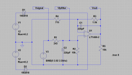
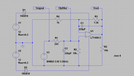
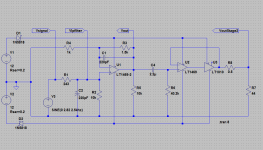
The LT Spice library doesn't have the njm2068 of course. I've substituted in the LT1469-2 which is one of Groner's suggested upgrades for an NE5532. The LT1469-2 is good for up to +/-18v also, so it works just fine to show the clipping issue at 12v vs. gain and input signal level.
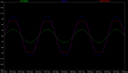
All plots are with +/-12V rails, assuming the "home" ac-powered case. The circuit is just for one channel since both are identical, of course. The legend for the plots are at the top of each and the file names (hover the mouse over each) shows the specifics.
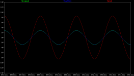
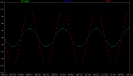
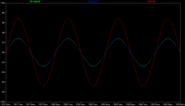
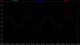
The first set of plots are with the original 3.1x gain setting with the 715R resistor. The first plot is with Vin = 2Vrms = 2.82Vpeak input at 2Khz. No clipping (the output is red). The second plot then is for Vin = 2.7Vrms = 3.82Vpeak input at 2Khz. The clipping on the output is apparent.
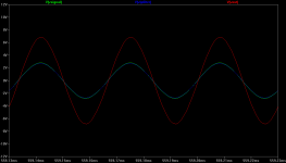
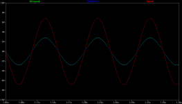
The second set of plots are with the new 2.5x gain setting with a 1k resistor. The first plot is with Vin = 2Vrms = 2.82Vpeak input at 2Khz. No clipping. The second plot then is for Vin = 2.7Vrms = 3.82Vpeak input at 2Khz. No clipping this time.
The final two plots are the new 2.5x gain with 2Vrms in at 10hz and 30Khz.
Here is the gain issue graphically.
The LT Spice library doesn't have the njm2068 of course. I've substituted in the LT1469-2 which is one of Groner's suggested upgrades for an NE5532. The LT1469-2 is good for up to +/-18v also, so it works just fine to show the clipping issue at 12v vs. gain and input signal level.
All plots are with +/-12V rails, assuming the "home" ac-powered case. The circuit is just for one channel since both are identical, of course. The legend for the plots are at the top of each and the file names (hover the mouse over each) shows the specifics.
The first set of plots are with the original 3.1x gain setting with the 715R resistor. The first plot is with Vin = 2Vrms = 2.82Vpeak input at 2Khz. No clipping (the output is red). The second plot then is for Vin = 2.7Vrms = 3.82Vpeak input at 2Khz. The clipping on the output is apparent.
The second set of plots are with the new 2.5x gain setting with a 1k resistor. The first plot is with Vin = 2Vrms = 2.82Vpeak input at 2Khz. No clipping. The second plot then is for Vin = 2.7Vrms = 3.82Vpeak input at 2Khz. No clipping this time.
The final two plots are the new 2.5x gain with 2Vrms in at 10hz and 30Khz.
Attachments
-
 O2 signal path 1st stage 3.1x gain circuiit.png35.6 KB · Views: 993
 -
 O2 signal path 1st stage 3.1x gain 2.5khz 2Vrms in.png22.6 KB · Views: 973
 -
 O2 signal path 1st stage 3.1x gain 2.5khz 2.7Vrms in.png23 KB · Views: 946
 -
 O2 signal path 1st stage 2.5x gain circuiit.png35.5 KB · Views: 952
 -
 O2 signal path 1st stage 2.5x gain 2.5khz 2Vrms in.png22.8 KB · Views: 949
 -
 O2 signal path 1st stage 2.5x gain 2.5khz 2.7Vrms in.png21.3 KB · Views: 151
 -
 O2 signal path 1st stage 2.5x gain 30Khz 2Vrms in.png22.6 KB · Views: 160
 -
 O2 signal path 1st stage 2.5x gain 10hz 2Vrms in.png22.3 KB · Views: 158
Last edited:
added 2nd stage
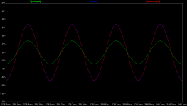
...and here is an approximation of the O2 second stage tacked on to take a look at clipping behavior end to end. I've had to use Linear Technology substitutes again, due to lack of njr models, from the LT Spice library.
The LT1469 (single, without the -2) is used since it is unity gain stable (-2 needs minimum gain of 2), driving a LT1010 150mA current buffer. The single LT1469 + LT1010 150mA pair "replaces" the two parallel njm4556 in one channel for simulation purposes, which are 70mA x 2 = 140mA.
The volume pot is on "full" in both plots for maximum signal transfer. The load is a resistive approximation of my 44R pair of Shure SRH-940s.
The first plot is of the original 3.1x gain is used with the 2.7Vrms input to plot clipping behavior end to end. The red is now the output of the second stage and blue is the output of the first stage.
The second plot is with the new 2.5x gain and a 2Vrms signal, showing no clipping end to end. Notice here the red output plot is sitting pretty much right on top of the first stage plot, a very good thing in current-buffer land. Note on the second plot that 7V peak is 5Vrms, which would be 5^2 / 44 = 550mW per channel, something my ears would never forget. Plenty of output at 44R with 2Vrms in and the first stage gain of 2.5x.
Lol - won't likely have a chance to log in much if any next week so probably won't see any posts/replies until the weekend.
...and here is an approximation of the O2 second stage tacked on to take a look at clipping behavior end to end. I've had to use Linear Technology substitutes again, due to lack of njr models, from the LT Spice library.
The LT1469 (single, without the -2) is used since it is unity gain stable (-2 needs minimum gain of 2), driving a LT1010 150mA current buffer. The single LT1469 + LT1010 150mA pair "replaces" the two parallel njm4556 in one channel for simulation purposes, which are 70mA x 2 = 140mA.
The volume pot is on "full" in both plots for maximum signal transfer. The load is a resistive approximation of my 44R pair of Shure SRH-940s.
The first plot is of the original 3.1x gain is used with the 2.7Vrms input to plot clipping behavior end to end. The red is now the output of the second stage and blue is the output of the first stage.
The second plot is with the new 2.5x gain and a 2Vrms signal, showing no clipping end to end. Notice here the red output plot is sitting pretty much right on top of the first stage plot, a very good thing in current-buffer land.
Note on the second plot that 7V peak is 5Vrms, which would be 5^2 / 44 = 550mW per channel, something my ears would never forget. Plenty of output at 44R with 2Vrms in and the first stage gain of 2.5x.Lol - won't likely have a chance to log in much if any next week so probably won't see any posts/replies until the weekend.
Attachments

Last edited:
First, thanks agdr for the sims! I based my numbers off real measurements. On AC power it's pretty easy. On battery power, however, the clipping point is battery voltage dependent. But we seem to be pretty close to being in agreement.
NEW FILES! - Revised files can be found in the O2 Files & Resources section and there are also now PCB files!
IMPORTANT - For anyone wanting to rush out and get boards made, you might want to hold off at least a few days. Extra sets of eyes might catch something I missed. Also, I should have more information soon about the availability of the board from one or more commercial sources. I know some have also talked about a group buy.
DESKTOP AMP - I believe the trade offs I made with the O2 in the interest of cost, size, and portability are worthwhile. I'm not aware of another portable amp that can do a better job overall--let alone for under $40 - $100. But...
There are things that can be improved in a desktop version. One of those is changing the gain structure to eliminate the input overload issue. In the O2 there simply isn't room to solve the problem without significantly hurting the performance.
Eliminating the batteries frees up lots of board space and removes $11+ from the total cost. That space, and the $11, can be put to good use improving the audio performance still further.
CHOICES - If you intend to use the O2 only where there's AC power, and you're not in a hurry, you might want to wait for the Desktop version.
COST - I don't know where the total cost will come in for an upgraded desktop version. The biggest issue will be the front and rear panels if you don't want to drill your own. Needing two panels instead of one will add around $20 to the total cost. I would expect the complete desktop amp to still be well under $130 and, if you get clever with the enclosure, you could probably build one for under $70.
TIMING - I also don't know when I'll get the desktop design published. At least I don't need to write another 40,000 words documenting it! I'll mostly just note where it differs from the O2. Still, there will likely be a couple spins of the PCB, prototypes built, lots of measurements have to be made, and there still will be a lot to document and write up. With the O2 cat already out of the bag, the desktop version is likely to be a more collaborative effort.
MORE DETAILS - I'll be sharing more details about the desktop version soon to see what everyone thinks. I have a bit more work to do first to know what all will be possible keeping some basic constraints in place.
Ehhemmm...
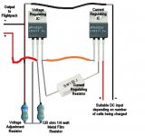
I really wish you would reconsider on the NiMh batteries though. LiFePO4 are really much better and just as cheap. Charging conditions are slightly more stringent. Two voltage regulators and a few resistors are all one needs to setup a voltage and current controlled charging solution similar in function to the one you have there.
I realize that is quite a crude example. It is feasible though. 6s center tapped is just the ticket. It is less likely to become imbalanced because it is fewer cells in series. The 9v NiMh are 8 in series and you are adding another 8 for dual PS. 6 vs 16 is a better proposition.
All of this nonsense about batteries burning up has got to end sometime. Have you ever seen A NiMh cell with an internal short? It's fireworks much the same.
Attachments

First, thanks agdr for the sims! I based my numbers off real measurements. On AC power it's pretty easy. On battery power, however, the clipping point is battery voltage dependent. But we seem to be pretty close to being in agreement.
NEW FILES! - Revised files can be found in the O2 Files & Resources section and there are also now PCB files!
IMPORTANT - For anyone wanting to rush out and get boards made, you might want to hold off at least a few days. Extra sets of eyes might catch something I missed. Also, I should have more information soon about the availability of the board from one or more commercial sources. I know some have also talked about a group buy.
DESKTOP AMP - I believe the trade offs I made with the O2 in the interest of cost, size, and portability are worthwhile. I'm not aware of another portable amp that can do a better job overall--let alone for under $40 - $100. But...
There are things that can be improved in a desktop version. One of those is changing the gain structure to eliminate the input overload issue. In the O2 there simply isn't room to solve the problem without significantly hurting the performance.
Eliminating the batteries frees up lots of board space and removes $11+ from the total cost. That space, and the $11, can be put to good use improving the audio performance still further.
CHOICES - If you intend to use the O2 only where there's AC power, and you're not in a hurry, you might want to wait for the Desktop version.
COST - I don't know where the total cost will come in for an upgraded desktop version. The biggest issue will be the front and rear panels if you don't want to drill your own. Needing two panels instead of one will add around $20 to the total cost. I would expect the complete desktop amp to still be well under $130 and, if you get clever with the enclosure, you could probably build one for under $70.
TIMING - I also don't know when I'll get the desktop design published. At least I don't need to write another 40,000 words documenting it! I'll mostly just note where it differs from the O2. Still, there will likely be a couple spins of the PCB, prototypes built, lots of measurements have to be made, and there still will be a lot to document and write up. With the O2 cat already out of the bag, the desktop version is likely to be a more collaborative effort.
MORE DETAILS - I'll be sharing more details about the desktop version soon to see what everyone thinks. I have a bit more work to do first to know what all will be possible keeping some basic constraints in place.
the portable one doesn't look really practical for me to replace my corda 2move, hence i'll pass. looking forward to the desktop version, rocketscientist! maybe i can finally utilize my unused laptop adapter for this project
Ehhemmm...
I really wish you would reconsider on the NiMh batteries though. LiFePO4 are really much better and just as cheap.
I'm an objective kind of guy so I try to analyze design choices in objective ways. I don't mean any offense, but here are my comments on LiFePO4 for the O2:
Please show me where I can get SIX high quality LiFePO4 cells (not the exploding no-name Chinese rejects on eBay) for under $11 (the cost of two NiMh 8.4V batteries) including shipping costs (you said "just as cheap").
Actually it's quite a bit less than $11 because you have to subtract all the extra charging/safety circuitry.
Then you have to find a way to mount and secure the six cells. And is there room for them and the extra charging circuitry in the existing enclosure?
The you have to redesign the entire PC board, that's already had a zillion hours invested in 3 revisions, to accommodate the new form factor of the batteries and the new charging circuitry.
Then factor in the DIY-unfriendliness and higher safety risks. I can short out a 9 volt Ni-Mh battery and it just gets hot and dies as the entire battery fully charged only has about 1.5 Watt/hours of total energy. LiFePO4 batteries are not nearly as polite.
And will the LiFePO4 amp work any better? It might have longer run time but there's already a 25+ hour version of the O2 for those who prioritize run time above all else. But will it measure better? I doubt it.
Let's get a group buy rolling!!
http://www.diyaudio.com/forums/group-buys/194708-o2-headphone-amplifier-gb.html
http://www.diyaudio.com/forums/group-buys/194708-o2-headphone-amplifier-gb.html
I do understand what you are saying about having to redo a whole crap ton of work. I know that isn't going to be a possibility for this generation of the O2 but it is something to think about.
I checked it out, and 3s LiFePO4 already packaged with protection PCB that protects against direct short/over/undercharge is $12.
LiFePO4 18500 Battery: 9.6V 800 mAh (3x18500 Flat, 7.68Wh, 7.0A rate ) with PCB & Polyswitch
So that's a $24 initial investment for a battery with more than two times the run time. It has also got close to a 3v edge over the NiMh. By the time you have replaced the NiMh batteries two times, the LiFePO4 would still have plenty of life left. Close to 500 more charges. That is over a year of everyday use. I bet it is actually more. That figure is low balled quite a bit.
$11 battery now, that will cost me 11$ to replace every year and gives half the run time at a lower voltage VS a $24 battery that I would need to replace every three years. Not looking good on price. Looks to me like the LiFePO4 is somewhere around 2/3 as expensive over time. Lets not even talk about charging time and internal resistance.
You have already got the LVC working. It could easily be changed to accommodate. The only thing missing is the power supply/charger. It won't be as easy as the clever half wave supply you have setup for the O2. It's not really that much harder either. Like I said, it's really my only critique of the design. It's not going to stop me from building one, but the battery is really the most important part of a portable amp.
Last edited:
- Home
- Amplifiers
- Headphone Systems
- The Objective2 (O2) Headphone Amp DIY Project