...
The half wave supply in the O2 generates some fairly significant peak charging currents in the primary diodes, filter caps, PCB traces, etc. That's because the caps "droop" a lot further between charging pulses than in a full wave supply. While the regulators do a great job of removing the resulting ripple from the rails they do nothing for the electromagnetic and E-fields (EMI) the charging pulses generate.
...
Can that be fixed with larger caps? [open setup no case needed]. The current will be the same but the voltage less
How about larger diodes? same current, but lower current density inside the diode.
Larger diodes, no. More/larger caps (which won't fit in the portable case) I haven't tested but I would expect that to help as the voltage will fall less between charging cycles. I'm going to be doing a lot more testing for the desktop amp. Right now I'm focused on making sure the O2 is ready for Prime Time.Can that be fixed with larger caps? [open setup no case needed]. The current will be the same but the voltage less
How about larger diodes? same current, but lower current density inside the diode.
No worries, you can use acrylic. The wire can just as easily go to the back panel and it still seems to work just fine. For the front panel you can just just use a lead clipping from one of the 1/8 watt resistors as the input jack ground pin is very close to the lower left corner of the front panel. For the rear panel you need to run an actual wire.
And it doesn't need the shielding of the front panel. I'm doing all my testing with no panel at all (just the screw) and the noise reduction on the dScope is dramatic and sufficient just grounding the "shell".
good to hear! i thought the wire needed to be connected to metal front panel to make the grounding works

I think what the amp mainly "wants" is a metal ground plane underneath the circuit board. So that's the most important part to have grounded. Ideally, the entire "shell" (top and bottom) are grounded to the input ground as described.good to hear! i thought the wire needed to be connected to metal front panel to make the grounding works
Very interesting amp and interesting reading in your blog. I find it in head fi just few days ago. Especially I like PS with real ground without double winding transformer, clever! I want to try volume after gain stage too, and especially your "new" opamps, probably I can change in future my usually building brick (OPA2134)
I just subscribed no PCB GB, however this is not exactly amp, I want.
First, I am not interested in batterys at all, desktop amp, RCA in, 6.3 out, probably other, better pot, if amp really is so good.
So, probably, parallel to your amp, I can make my own p2p desktop, based on your amp.
I have few questions:
going to only AC, I can eliminate "middle part" just diodes, el. caps, regulators and then amp part. Of course low ESR caps closer to chips.
I have 24V transformer, I plan to use 15V or 18V regulators (probably adjustable). How high can I go with 24V transformer without degrading quality? I have experience only with classical bridge.
Higher voltage can solve input overdriving problem with higher gain and higher source too.
And one more question - I use mostly 300 ohm HD580, are there big reason to use parallel opamps in output, in this case? I think current is enough with one, on the other hand, they alway say HD580 sound best at low output impedance.
@Zigis, glad you liked the blog
You might want to wait... I will be releasing a desktop amp with RCA, 6.3mm large headphone jack, AC only power supply, etc. soon! It will have a few other upgrades as well and will include the PC board layout, etc.
And yes, one 4556 (for both channels) is OK for 300 ohm headphones. In fact it's OK for 150 ohms and higher.
I wouldn't run the 4556 past +/- 15 volts. And not past 12 volts with loads < 150 ohms. If you have a 24 VAC center tapped transformer I would make a full wave bridge. If it is just one winding (2 wires, no center tap) you might exceed the input voltage of the regulators. My design is about +/- 30V unregulated (60 volts total) with a 20 volt transformer. 24 volts would put that up to +/- 36 volts. Most regulators are only safe to 30 or 35V.
@RocketScientist - This looks like a great project, and I'm looking forward to building it.
I have a question for you...
I currently use an MP3 player in the car to feed audio into the AUX input on my head unit. But in order to get a decent speaker output, I have to crank the volume of the source and the head unit to 100/80% respectively, or amplify the signal with a headphone amp.
I've experimented with a variety of DIY amps (CMOY, mini^3, vAmp) and had decent results, but I like the overall design of the O2 and would like to try that as an option.
My question is this: Would it be possible to power the O2 using the vehicle's 12V system? Since the amp would live in the vehicle all the time, swapping out 9V batteries is less than ideal, and running an inverter just to power a wall wart seems a bit ridiculous.
I understand that the power supply in a vehicle is pretty noisy, so I figure that's one area that might be limiting. But beyond that, is there anything that wouldn't work using that method?
Thanks again for your help. Regardless of whether this works in the car, I'm still going to build one for portable use.
Thanks for fast and detailed answer.
I have one 1x24V wallwart type transformer from Christmas tree light or something like this.
Yes, I quick see fixed regulators in Farnell, really too low input voltage limit, never thinking about this before. However most 317/337 have 40V input, so I still can use my transformer.
It is easy make right PS with right (double winding) transformer.
What i like in your PS - it is possible to use remote transformer, for lower noise and smaller amp on desktop and still use simple 5.5/2.5mm jack. Small point, but agreeably
What happen wen 4556 ran with higher voltage? (max 18V)
@tschuss
I don't think, you can use cars's 12v for amp (cmoy or O2,any) Problem, at least with simple CMoy is - car ground is CMoy's negative (-), you can't connect it together. Maybe RocketScientist know the way to create negative -12V from car's +12V.
to drive AUX in you don't need O2 powerful output stage, just gain stage, without pot.
@Zigis - I know that you cannot use the car's system for the cmoy due to the floating ground in that amp, but my understanding (perhaps a false understanding) was that the O2 doesn't use that type of ground.
I will readily admit my lack of knowledge in this area. I'm more of a mechanical guy, so I have to rely on the genius of others to fill in such things.
Thank you for your help.
I will readily admit my lack of knowledge in this area. I'm more of a mechanical guy, so I have to rely on the genius of others to fill in such things.
Thank you for your help.
tschuss, the O2 is overkill for your car mp3 preamp. It would work, yes, but something like the cmoy is probably enough for what you need. I would look into something like these Murata DC-DC converters. Get the appropriate amperage and somewhat higher voltage than required. Use pos & neg voltage regulators to clean it up a bit and set the desired supply voltage. An OPA2134 ~3x gain stage should put you in business. Or run the O2 from the converter; you could get by with just one 4556 at the output.
For any readers who are interested in the O2 but not ready to take the complete DIY plunge, I have posted a offer for a build service here:
http://www.diyaudio.com/forums/vend...-headphone-amp-build-service.html#post2680290
http://www.diyaudio.com/forums/vend...-headphone-amp-build-service.html#post2680290
@RocketScientist - This looks like a great project, and I'm looking forward to building it.
I have a question for you...
My question is this: Would it be possible to power the O2 using the vehicle's 12V system?
Regardless of whether this works in the car, I'm still going to build one for portable use.
If you're going to build one for portable use anyway it could serve "double duty" and save you from having to build something different just to solve your car gain problem. The easiest solution would be an isolated DC-DC converter module with an input voltage range of at least 12 - 18 VDC (and even higher is better as car electrical systems can have huge transients). The output should be 24 volts at 25 mA or higher.
You can add a DC power jack (just like the AC power jack but panel mount) on the back panel above U2, and wire it with 1N5818 isolation diodes and probably 80 - 100 ohm resistors to the positive terminal of BT1 and the negative terminal of BT2.
That lets you "float charge" the O2's batteries with a single 24 VDC source. With the O2 is turned on, the quiescent (idle) current for the amp will be supplied by the external DC-DC converter in your car. If you tried to drive headphones the extra current required would come from the batteries. But you're driving a high impedance load so that's not an issue.
The only downside is you need to leave the O2 on when the 24 VDC source is used unless the batteries are low and you want to charge them for a few hours. The reason is the charge current will be around 20 - 25 mA which is fine for a few hours if the batteries are low but will eventually overcharge them. The AC home adapter can still be left connected indefinitely.
EASIER OPTION: Depending on what headphones you plan to use, you could also just build the long run-time version of the O2 and just run it from battery in the car. Under those conditions it should run 30 - 40 hours from battery which is a lot of driving.
Thanks for fast and detailed answer.
However most 317/337 have 40V input, so I still can use my transformer.
That should work, but still check what the maximum unloaded voltage works out to with your transformer. They really vary a lot. Also, you'll need 50V electrolytic caps as 35V won't be enough. And the 317/337 will need heatsinks.
What happen wen 4556 ran with higher voltage? (max 18V)
See the section on dissipation in O2 Circuit Description. The short answer is power dissipation goes up exponentially with supply voltage because P=V*V/R. So at 12 volts it's 144/R and at 18 volts it's 324/R or 225% higher. The plastic DIP8 package will get too hot.
For any readers who are interested in the O2 but not ready to take the complete DIY plunge, I have posted a offer for a build service here:
http://www.diyaudio.com/forums/vend...-headphone-amp-build-service.html#post2680290
Excellent! Thanks MrSlim!
Last edited:
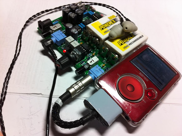
I am a diyer from Hong Kong, and I have built an O2 Amp by following the PCB and parts on the project. Sound quality of O2 is really good in default setting. And the quality of sound improved a lot after change the IC. Thank you for sharing a good design of Amp.
Below is my work.
Below is my work.
I am a diyer from Hong Kong, and I have built an O2 Amp by following the PCB and parts on the project. Sound quality of O2 is really good in default setting. And the quality of sound improved a lot after change the IC. Thank you for sharing a good design of Amp.
You're welcome. That was fast!
Where are the MOSFETs (Q1 and Q2)?
Also, there are some changes... did you change C16 and C21 to 0.022 uF?
I am a diyer from Hong Kong, and I have built an O2 Amp by following the PCB and parts on the project. Sound quality of O2 is really good in default setting. And the quality of sound improved a lot after change the IC. Thank you for sharing a good design of Amp.
Below is my work.
that is cool work MoonL!!
can you elaborate the sound quality compared to other amp you have maybe?
One of my friend who also built O2 is starting to make a case for O2.
Just want to share the design of the case.
Material used is wood and copper
Just want to share the design of the case.
An externally hosted image should be here but it was not working when we last tested it.
An externally hosted image should be here but it was not working when we last tested it.
An externally hosted image should be here but it was not working when we last tested it.
Material used is wood and copper
An externally hosted image should be here but it was not working when we last tested it.
Material used is wood and copper
You need to plate that copper before starts to oxidate ...
Anyway I like it very much!
If you're going to build one for portable use anyway it could serve "double duty" and save you from having to build something different just to solve your car gain problem. The easiest solution would be an isolated DC-DC converter module with an input voltage range of at least 12 - 18 VDC (and even higher is better as car electrical systems can have huge transients). The output should be 24 volts at 25 mA or higher.
You can add a DC power jack (just like the AC power jack but panel mount) on the back panel above U2, and wire it with 1N5818 isolation diodes and probably 80 - 100 ohm resistors to the positive terminal of BT1 and the negative terminal of BT2.
EASIER OPTION: Depending on what headphones you plan to use, you could also just build the long run-time version of the O2 and just run it from battery in the car. Under those conditions it should run 30 - 40 hours from battery which is a lot of driving.
Thank you very much for your helpful reply. I do appreciate it. My whole quest has been to find a solution that turns on and off with the car, and is something that I can package into the console so I can "plug & play" without having to think about batteries or having a separate piece of equipment sliding around.
I might be trying to use the wrong tool for the job, but as I said, I'm more of a mechanical guy, so I haven't been able to find (or create) the right solution.
I've got a few boards on order, and really enjoy making this kind of stuff, so even if I can't make it work, I can always give the extras away as nice Christmas gifts. My Dad loved the mini^3 I gave him last year, and he just told me the battery doesn't work any more, so this would be a nice upgrade for him. And I'll build another one to use with my 'phones, so it's all good.
As I said before, my friend is making a case for O2, and he had already make a prototype. Follow is the steps how he made the case, so you can also try to work out your own case by yourselves
Frist, drill 3mm holes on the wood pecies for holding the PCB
Next, drill 5.5mm holes on wood pecies (used to stick the wood pecies together to form the case)
Start to cut the wood according to the design
The cut wood pecies for making case
Try to insert the PCB board on the wood pecies
Prototype of case is as below
Frist, drill 3mm holes on the wood pecies for holding the PCB
An externally hosted image should be here but it was not working when we last tested it.
An externally hosted image should be here but it was not working when we last tested it.
An externally hosted image should be here but it was not working when we last tested it.
Next, drill 5.5mm holes on wood pecies (used to stick the wood pecies together to form the case)
An externally hosted image should be here but it was not working when we last tested it.
Start to cut the wood according to the design
An externally hosted image should be here but it was not working when we last tested it.
An externally hosted image should be here but it was not working when we last tested it.
An externally hosted image should be here but it was not working when we last tested it.
An externally hosted image should be here but it was not working when we last tested it.
An externally hosted image should be here but it was not working when we last tested it.
The cut wood pecies for making case
An externally hosted image should be here but it was not working when we last tested it.
Try to insert the PCB board on the wood pecies
An externally hosted image should be here but it was not working when we last tested it.
An externally hosted image should be here but it was not working when we last tested it.
An externally hosted image should be here but it was not working when we last tested it.
Prototype of case is as below
An externally hosted image should be here but it was not working when we last tested it.
- Home
- Amplifiers
- Headphone Systems
- The Objective2 (O2) Headphone Amp DIY Project