
Now of course specs are one thing and real-life performance is another. Not too many free lunches out there. That's one thing people should have learned from Capacitor Plague.RocketScientist - good find on those Lelon 470uF caps in the new spreadsheet BOM! 50% higher ripple current rating and 50% more rated life for 1/2 the cost. I had missed those.
Pictures
Hi,
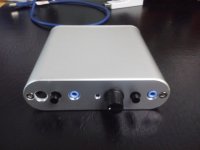
Just wanted to post some pictures. I find it cute, considering that is done by hand. I would comment that this is really an easy project, I did it, no brainer in two hours, ordering parts from Mouser. Case was purchased locally, and needed a bit of filing to allow the connectors in.
If you are wondering why you should not DC couple a battery operated preamp with something is not battery operated, look at the other picture. Still not sure what happened, but no other damage than what you see.
I had the signal generator of the pico tech 4262 connected to the O2 and the output of the O2 connected to a test channel of the F5.
I also did some measurement with my limited instrument, and this thing behaves really well. I also like the sound with my Audio Technica ATH-900 (40 ohm).
Thanks,
Davide
Hi,
Just wanted to post some pictures. I find it cute, considering that is done by hand. I would comment that this is really an easy project, I did it, no brainer in two hours, ordering parts from Mouser. Case was purchased locally, and needed a bit of filing to allow the connectors in.
If you are wondering why you should not DC couple a battery operated preamp with something is not battery operated, look at the other picture. Still not sure what happened, but no other damage than what you see.
I had the signal generator of the pico tech 4262 connected to the O2 and the output of the O2 connected to a test channel of the F5.
I also did some measurement with my limited instrument, and this thing behaves really well. I also like the sound with my Audio Technica ATH-900 (40 ohm).
Thanks,
Davide
Attachments


For what it's worth, I've used 3 different caps on the unregulated side of the supply in the O2, including the Lelons, and have not been able to measure any difference in the ripple performance, etc. Compared to many applications, the caps run cool (especially the pair closer to the power jack). And it's not a demanding application.Now of course specs are one thing and real-life performance is another. Not too many free lunches out there. That's one thing people should have learned from Capacitor Plague.
Electrolytic capacitor death is most famous on PC motherboards. The caps in the 40 - 150 amp CPU core power supply, that sit right next to the hot CPU heatsink and MOSFETs, are famous for dying after 3 - 5 years. If those motherboard caps can last that long with 7x24 use in a 45C+ environment with extreme ripple currents, I think the O2 is on solid ground to outlive many of the people who build one.
For those who don't have one, it's worth pointing the entire O2 runs far cooler than lots of other headphone amps that don't perform as well--most notably tube amps, single-ended MOSFET amps, and various Class-A amps. Despite everything being a snug fit, the B2-080 enclosure never gets more than lukewarm (and then only over the regulators) on AC power and is stone cold on battery power.
Component costs fluctuate wildly even month-to-month based on inventory levels and other factors. The original Nichicon 470 uF caps were $0.08 each and went up to over $0.40 each--same part. So based on price alone do you think they're better or worse than the $0.25 Lelon caps?
The more critical power supply caps in the O2 are the 220 uF C8 and C9. They're special low impedance types chosen specifically for their specs. Unlike the 470uf caps, C8 and C9 do have a measurable effect on the audio performance.
@Nikon1975 if you put enough of those NJM chips in a pan with some hot oil, and add some butter and salt after they've all popped, them are good eatin'! ")
I'm guessing you created some sort of ugly ground loop with your test equipment. If both channels were connected you might want to replace the other 4556 as well just in case.
Nice looking amp! I like the rounded case!
I'm guessing you created some sort of ugly ground loop with your test equipment. If both channels were connected you might want to replace the other 4556 as well just in case.
Nice looking amp! I like the rounded case!
Thanks,
No, only one channel was connected. My scope has a generator that can give only 1V output, and I was thinking of using the O2 to have a bit more voltage to test amps with not much gain. Maybe I have to think it better, probably putting coupling caps on the cable I use for testing would make.
D.
Unlike amps with virtual grounds, the O2 has all the grounds at the same "true ground" potential (assuming you're not using a bench DC supply to run it). So there shouldn't be any DC risk with ground loops--i.e. coupling caps may not help. And you can safely put up to +/- 7 volts of DC into the input of the O2 without harm and none of it will make it to the 4556 op amps or output. So DC on the input is not a problem.
One big problem with Pico's instruments is most of them share the instrument ground with the PC's USB ground. And you mentioned other test equipment as well. If whatever was hooked to the O2's output was in any way connected to the PC or back to AC-line ground, you created a mammoth ground loop and all bets are off. You might have made it self oscillate that way.
It's also possible the input of the O2 was grounded back through the USB connection and whatever was on the output had significant AC leakage current (that "fuzzy" feeling when you touch something running on AC power that's not grounded). If you measure from such equipment to ground it's not uncommon to find 60+ volts of AC but at a high impedance so it's not actually dangerous to humans, but it can be to electronic gear caught in the middle.
That's why I use isolated scope inputs, isolated generator outputs, and why the dScope has fully isolated inputs and outputs not just from ground but from each other. Oftenn with grounded equipment like the Picoscope, the only way to break that loop is to use an audio ground loop isolator with a transformer in it (which will somewhat degrade the signal) or, and this is pretty cheesy, run the Picoscope from a battery powered laptop.
And, just an FYI, the same thing can happen with much more spectacular results when testing audio power amps using USB grounded test equipment.
yeah thats pretty useless isnt it? sharing usb ground along with its infamous switching spikes, with sensitive instrumentation? is that for real? could you use something like an ASDL driver, LVDS, or some other type of active BALUN in the middle rather than a transformer similar to what TP is using for the teleporter i2s transceiver? i know to some extent you will end up measuring that, but if its a known quantity perhaps you could adjust to it?
thats not a suggestion btw, but a real query as i'm looking into measurement equipment for the next round of tools purchases along with a variac
btw Davide: is that little case from that local mob i linked you the other day? i just recieved their catalogue and theyve got some pretty cool stuff and a massive range!! i wonder what sort of quality their custom milling/CNC services are
For what it's worth, I've used 3 different caps on the unregulated side of the supply in the O2, including the Lelons, and have not been able to measure any difference in the ripple performance, etc.
Lol - yeah those beefed up parameters of the Lelons are not "needed" in any way for this particular circuit. I'm mainly impressed with the price. That is some smart shopping.
@qusp, this is getting OT, but the trick with transformers is the frequency range you want. They can work fairly well but only over a limited bandwidth. The audio transformers in the cheaper ground isolators have serious trouble below 100 hz and start to get weird above 10 khz. The $100 ones from Jensen are much better but still have their limits. RF transformers are useless at audio frequencies.
There are USB isolators but the ones that work with USB 2.0 cost more than some of the Picoscopes. Most only work as 12 Mbps not 480 Mbps. All the USB scopes I know of with isolated USB only run at 12 Mbps and have really slow screen updates--which is especially bad for say trying to follow a music signal to observe clipping, or whatever. There's more about scope trade offs, etc. in my (rather dated in terms of my blog) Testing Methods article.
There are USB isolators but the ones that work with USB 2.0 cost more than some of the Picoscopes. Most only work as 12 Mbps not 480 Mbps. All the USB scopes I know of with isolated USB only run at 12 Mbps and have really slow screen updates--which is especially bad for say trying to follow a music signal to observe clipping, or whatever. There's more about scope trade offs, etc. in my (rather dated in terms of my blog) Testing Methods article.
REGULATOR FAILURES - I've been told there's some grumbling on Head-Fi about regulator failures with the O2? Has anyone here had a problem? 78XX and 79XX regulators are normally about as fragile as anvils.
I get lots of O2 related emails and private messages every day and not a single one has mentioned regulator failures. So it's a bit odd the fuss is ONLY at Head-Fi where a significant gang has tried to do everything they can to make the O2 look bad to protect various interests there.
The regulators in the O2 are thermally protected. Even if someone manages to get them too hot, they should just temporarily shut down. The only obvious way to fry them would be to use more than a 20 VAC wall transformer and exceed their maximum input rating. Obviously that's hard to do accidentally. And the impedance of the wall transformer and 2000 uF of primary capacitance forms a natural RC filter against line transients.
The only other thing I can think of is if someone used the wrong diodes (like the Schottky parts) for D3 and/or D4 and they shorted and are pumping AC into the regulators. But I would think the caps would ooze goo all over if that were the case.
I'm blocked from head-fi, so if anyone here cares to perhaps direct those concerned to post here or contact me via the blog, that would be great. Something seems very odd.
@RocketScientist - you seem to have hit on the one downside of the project - you release a design for a whole bunch of people with varying skills to build, and when some of them end up with something that doesn't work, they blame you, the design, the components - anything but their own incompetence!
I don't think you could have made the build process any easier, this is the best-documented project that I can ever recall seeing, but some of the queries posted on this forum would suggest that not everyone has read your build instructions...
What happens if they have been mounted too high so that one or both of the metal tabs contact the case?
I don't think you could have made the build process any easier, this is the best-documented project that I can ever recall seeing, but some of the queries posted on this forum would suggest that not everyone has read your build instructions...
78XX and 79XX regulators are normally about as fragile as anvils.
What happens if they have been mounted too high so that one or both of the metal tabs contact the case?
Last edited:
RocketScientist, the person who vocally reported faulty voltage regulators on head-fi has been directed here on numerous occasions by various contributers to that thread. TBH, the first diy O2 thread was locked and the second is now a bit of a joke (though quite entertaining to read).
It'd be quite surprising if the person who reported the faults posted here. His overall view of the O2 and yourself has been quite negative, to put it politely.
Paul
It'd be quite surprising if the person who reported the faults posted here. His overall view of the O2 and yourself has been quite negative, to put it politely.
Paul
Last edited:
I posted in there regarding the regs simply because there does seem to be a number of similar failures of the same part with the same symptoms, that to me deserves a closer look, thats all. i dont think anyone is questioning the thoroughness of the documentation and preparation for this project, I know i'm not and certainly any reasonable person wouldnt; but you just dont know until real numbers of people out in the real world build a kit and do remember thats what it is, not a design that will be built under consistent conditions
as mentioned there is a large number of people with different skills, different access to tools, different access to parts (some of which may even end up being sold fakes) and if there is a number of similar problems i would say although its probably not the designers fault, it is a fault. nothing that cant be recovered even if it does turn out to be linked to the design. with this many kits out there, i would be surprised if there wasnt a problem.
could it be linked to improper handling of the parts before they were packed?
also i think its unwise to use words like grumbling
Last edited:
I need to attend to building my own O2.
People that bought their kits from me have already finished theirs and here I am, with nothing to show...
I think I'll go out and buy a new soldering station first, though.
A Weller station from the 80s is good and well, but I think a shiny new Ersa i-Con 1 is in order...
(Or would you guys recommend strongly against it or strongly FOR something else?)
@qusp:
I just don't think that the "problem" would be this limited if it were caused by the design.
Of course the design has flaws. There is no such thing as a perfect design.
You can even argue about a simple piece of wire and if its perfect, so a design as complex as this... you get the drift.
But the "imperfections" are documented in the blog, the board layout and all the other information that is available.
But lets wait and see what that turns into.
Last edited:
But lets wait and see what that turns into.
exactly..
possibly unwise to claim victory after less than one month in service of the official kits/pcbs; my guess is RS designed this for much more than that.
and more specifically at you: to attempt to simply shift blame the builders by doing things like putting the word 'problem' in inverted commas, will not go well, especially since it was promoted by many as a design my cat could successfully finish because of the documentation and support.
give it a closer look first and that appears to be what RS is keen to do, which is all i'm saying. there areat least a couple others that have reported the same issue, hopefully one will come here so it can be gone over. good chance it really will turn out to be user error, but it shouldnt be assumed
Last edited:
Jokener I assembled this kit with an Ersa 'gun', where the only temperature control is the trigger, so I doubt you can have problems with anything
Anyway, I'd like to report that I haven't managed to blow this up yet, which is super-odd, given my track record so far.
I didn't even manage to short the S2 to the via, even though I forgot about the potential issue. It's been plug&play so far, absolute breeze to assemble and extremely enjoyable to listen to.
I went trough a pair of crappy earbuds, by clickng on high gain, volume to the max and leaving it there until they melted. Just to see how that'll go.
So far so good, now I'm running its batteries to depletion to test the shutdown. It takes me quite a while already.
I don't know how anybody can blow anything up doing this amp
it's like 1 on a scale of 1 to 5
if you are not careful and put stuff in the wrong place, or don't check for shorts or fitment issues, then don't blame the board
I built over 10 now and every one works 100%
no rectifier issues!
-joe
it's like 1 on a scale of 1 to 5
if you are not careful and put stuff in the wrong place, or don't check for shorts or fitment issues, then don't blame the board
I built over 10 now and every one works 100%
no rectifier issues!
-joe
@Jokener - if you're going to use 60/40 solder then any decent small soldering iron will be fine - however, if you're going the lead-free route, a temperature-controlled iron is pretty much essential.
My recommendation would be to stick to 60/40, it melts at a much lower temperature, and thus is less likely to cause component damage during assembly.
My recommendation would be to stick to 60/40, it melts at a much lower temperature, and thus is less likely to cause component damage during assembly.
- Home
- Amplifiers
- Headphone Systems
- The Objective2 (O2) Headphone Amp DIY Project