Thank you for pointing this out! However, the datasheet states that the diode is protection against input short-circuit, it provides the path for the output cap to discharge around the regulator rather than into it. It shouldn't be necessary unless you actually do short circuit the input?The regulators are prone to failure as reverse biased diodes from output to input and output to ground are not provided. Mine failed too, so I attached these on the underside of the PCB
Input shorted means the input capacitors are fully discharged, acting like a short, while the output capacitors are still holding charge. This is like applying voltage at the output of regulators. Big no-noThank you for pointing this out! However, the datasheet states that the diode is protection against input short-circuit, it provides the path for the output cap to discharge around the regulator rather than into it. It shouldn't be necessary unless you actually do short circuit the in
Scenario 1 Since instead of bridge rectifier, 2 diodes are used as a voltage Doubler to create bipolar supply. So, during power ON, either the +ve or the -ve regulator turns ON first, depending upon the polarity of the first half cycle
Scenario 2 During power off the large output capacitors may try to discharge thru the regulators
Two diodes, D1 and D2 should be connected for reverse bias protection of the regulators. D3 and D4 should be connected for output polarity reversal protection. They also prevent outputs from being latched up during power ON
Last edited:
I will get back to you once I have access to variac , so that I can set output AC voltage to exact 12V AC, and then measure the drop in view of worst-case scenario full load current as demanded by O2I understand that 12V declared and 14V real is okay. However, we all have different voltages in our houses. I mean real measured 12V is not enough.
Just spent a few days reading up about your project. Even though I dont use or own headphones. Im tempted to build this just so I can justify buying a nice pair of headphones. lol
Very well documented project. Learned so much. Thank you. Im building a preamp for my Akaki HT350 turntable. Your inputs on various op amps was an eye opener.
Very well documented project. Learned so much. Thank you. Im building a preamp for my Akaki HT350 turntable. Your inputs on various op amps was an eye opener.
You do know that any modern power bank can be made to output voltages such as 5v / 9v / 12 v.Thanks Sofaspud,
That goes well beyond what my knowledge allows me to do and I don't think I find a power bank with 1x5 + 2x9V outputs...
My MI 2000 MAH does it. You will need to emulate a fast charge circuit i.e. the power bank must think its talking to a phone or tablet that supports quick charge. Mygot bat for such projects are the large 5000 mah bats like the 21700 or larger bats. You also get 9 volt bats which can be recharged and are powered by lipo bats i.e. 3.7 to 4.2 lipo packs. Converting a single d/c to +- is easy as somebody has already explained.
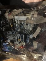
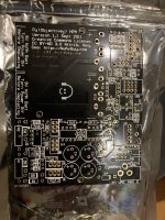
I was rummaging through my parts bin and found an OG set of parts and v1.1 PCB!
I had bought 3 sets of everything and built myself and a friend one of these amps and then forgot I had another set.
This was back when Nwavguy was still alive and kicking and I think the PCB has had some changes since.
Is this worth anything? I still have my original and it still works a treat with my HD600s
Attachments
Last edited:
I started playing with my O2 amp that I stowed away since the move from the office to home because of covid. The O2 amp was previously used everyday for years before alongside an ODAC.
One thing that keeps me from using it at home is the massive power supply. It was was nicely hidden away at work and never moved but now at home, I don't have a permanent workspace so I move about quite a lot. Now using the battery makes a lot of sense but all my 9v are dead. I have a bunch of voltage boost circuits that can be set to 9v. Would running two of those off one big battery work? Of course I wouldn't use the AC adapter anymore.
Using just one battery is ideal for charging. I ran 2x 2s packs before but it was too much hassle to charge.
Last edited:
canter point of the 2 9V batteries in series is the grounding point (real ground), I don't think your setup will workI have a bunch of voltage boost circuits that can be set to 9v. Would running two of those off one big battery work? Of course I wouldn't use the AC adapter anymore.
Using just one battery is ideal for charging. I ran 2x 2s packs before but it was too much hassle to charge.
Hi, I would be intersted. As I am new on the forum I am not allowed to send PM but you can contact me if it is still actual.I was rummaging through my parts bin and found an OG set of parts and v1.1 PCB!
I had bought 3 sets of everything and built myself and a friend one of these amps and then forgot I had another set.
This was back when Nwavguy was still alive and kicking and I think the PCB has had some changes since.
Is this worth anything? I still have my original and it still works a treat with my HD600s
Could I use this one as a replacement for the DC Power Jack? Unfortunately the Mouser one is discontinued and I fried mine because my solder ironing was touching it...
I need some help with troubleshooting, please.
I'm finishing assembly of a previously started O2. As I recall, it had a channel balance problem.
So last weekend, I measured all of the resistance values as specified in the installation guide as well as the voltages. All voltages except one checked out okay (one of the headphone voltages was 8mv vs "< 8mv" so not wildly out of spec).
However, several of the resistor values didn't match:
R21 - 913 ohms (vs R17 at 1K)
R16 - 1.5K (vs R22 1.3K)
R5 - 235K (vs ~100K)
R25 - 400K (vs ~330K)
Before posting here, I re-read all of the instructions, including the info about R21 and S2. I was pretty sure it was something to do with R21 and S2, but I didn't actually do anything.
This weekend, I started to work on it again. Before I started desoldering, I decided to re-measure all of the resistance values. And now they're different and I'm very confused.
I checked that the amp was unpowered but switched on, U2 in but U1, U3, U4 out.
Now, here's what I have:
R21 - bang on 1K (so the same as R17)
R22 - now 1.5K (same as R16, but neither are the 1.3K specified)
R5 - 91K (so closer to ~100K)
R25 - 311K (again closer to ~330K)
Any suggestions on what to do next?
I understand I cannot check single resistor values in circuit. But I'm not trying to do that. I am trying to check resistance values in circuit (as in the aggregate resistance including other components in the circuit), which is what the troubleshooting guide put together by the circuit designer recommends.
http://lh4.ggpht.com/-YZ8GUyJYrJ0/T...20resistances%2520no%2520power%255B3%255D.png
From this page: http://nwavguy.blogspot.com/2011/08/o2-details.html.
http://lh4.ggpht.com/-YZ8GUyJYrJ0/T...20resistances%2520no%2520power%255B3%255D.png
From this page: http://nwavguy.blogspot.com/2011/08/o2-details.html.
This has cropped up before It doesn't work. One big variable is the actual meter used and the test voltage it applies at the probes on resistance ranges and the polarity (which way around you place the probes).
If you have a channel balance issue then there are some easy things you can check.
You can remove U1 and quickly link pin 3 to pin 1 and pin 5 to pin 7. That removes the gain stage and allows the outout stage to function on its own. It has a voltage gain of one and there should be no channel imbalance in that state.
It doesn't work. One big variable is the actual meter used and the test voltage it applies at the probes on resistance ranges and the polarity (which way around you place the probes).If you have a channel balance issue then there are some easy things you can check.
You can remove U1 and quickly link pin 3 to pin 1 and pin 5 to pin 7. That removes the gain stage and allows the outout stage to function on its own. It has a voltage gain of one and there should be no channel imbalance in that state.
Hi everyone
I just registered to this forum. I have an O2 Amp since a little more than 10 years. Now it has broken down. I tried to find circuit plans and found some on the original NwAvGuy website. There is a documentation package, but it seems to be no longer accessible. Does anyone have a complete documentation of the O2 Amp?
Best
I bought one of these used, not working, that is the AC power only version.
It has a 1/4" headphone jack on the front panel that hits some caps and it
seems that they installed some with very long leads to try to make clearance
but it still does not fully clear.
It really looks like the board was designed for the battery version and with a
1/8" front panel headphone jack but does anyone know where the documentation
is for building the AC only version with a 1/4" front panel jack?
It doesn't seem like the 1/4" jack version can be made to work so my last resort will
be to install a 1/8" jack and use an external adaptor when using 1/4" headphones.
- Home
- Amplifiers
- Headphone Systems
- The Objective2 (O2) Headphone Amp DIY Project