Comparator issue
Hi, I've done the full build, and all the diagnostics
The power circuit is not working on battery with all the chips inserted. The output of U2 pin 1 is around 2.2-2.5V. This is low enough to turn on the gate to Q1, but higher than Vref (led) so that the 2nd comparator switches Q2 off. this results in about 5v DC on the output, due to the positive rail being on, and negative off.
I tested the circuit on AC works fine, correctly switches off both rails with R9 shorted
I tested on battery with U3/U4 removed, and it works fine. Tested the switch-off with either one battery removed or R9 shorted, both rails are either on or off.
Adding U3/U4 (more load) causes the issue.
Here are the voltage readings I'm getting in the bad state:
U2 rails: 8.1/-8.0
1,2,3: 2.2, ?? -6.3
5,6,7: -6.3, 2.5, -7.4
V across D7: 1.7, Vref: -6.3
R24: 2.1
Now the weird thing is, when I probe pin 2 (voltage divider point) with my DMM, the comparator starts working. Turning the amp off/on will reset to the bad state. After probing pin 2 and the negative rail turning on, the amp draws more power (15mA -> 22mA) the battery voltages dip, and the voltages change a bit:
U2 rails: 7.8/-7.4
1,2,3: -7.4, -5.4, -5.7
5,6,7: -5.7, -7.4, 4.7
V across D7: 1.7 Vref: -5.7
R24: -5.8
My guess is that in probing the voltages on bringup, I bridged some pins on U2 and shorted/broke it. Not sure if this has been seen, or if there could be another culprit.
Does the circuit work correctly on AC power with R9 NOT shorted?
The circuit should be good down to battery voltages of around -/+ 6.6 to 7 volts on U2.
A big clue is the fact that both comparators do not switch together which if happening is not a valid state. You should never be able to get a condition where one rail is on and the other not.
Is the comparator the correct type?
Are the FET's the correct type. This is most important due the gate/source voltage swing they experience?
Thanks for your response!
The part #'s are:
NJR NJM2903D
ON Semi FQU11P06TU
ON Semi FQU10N20CTU
Picked the IPAK version of the N-FET due to this note on the blog:
"Q1 AND Q2: These parts are worthy of a special note. Fairchild makes several suitable MOSFETs for both Q1 and Q2 but many are currently out of stock. I’ve provided substitutes in the parts list that are in stock but some are in a TO220F package rather than the desired, and much smaller, IPAK configuration."
The BOM TO22F part is: FQPF10N20C. Hopefully this is ok.
I recharged the batteries. These are Tenergy's that I have used in a cmoy before. After a fresh charge, the circuit was coming up in a the correct state for a bit. But then after running for 10-min or so, it started having the problem again. The batteries might just be too-old, but this is exactly the thing the circuit should be protecting against.
Even with the low-ish voltage, I'm measuring P2 higher (less negative) than P3, which should be an ON state for both rails. Keep in mind that once I probe P2, the circuit reverts to the correct behavior with both rails on. Even if I turn on the amp with the probe on P2 it will start up correctly.
Yes, it correctly transitions off/on with the short applied/removed. I see a max of 300mV DC on the unloaded outputs during the transition (cheap DMM, not scope). Also does the same on battery with U3/U4 removed (battery voltages stay higher).Does the circuit work correctly on AC power with R9 NOT shorted?
The part #'s are:
NJR NJM2903D
ON Semi FQU11P06TU
ON Semi FQU10N20CTU
Picked the IPAK version of the N-FET due to this note on the blog:
"Q1 AND Q2: These parts are worthy of a special note. Fairchild makes several suitable MOSFETs for both Q1 and Q2 but many are currently out of stock. I’ve provided substitutes in the parts list that are in stock but some are in a TO220F package rather than the desired, and much smaller, IPAK configuration."
The BOM TO22F part is: FQPF10N20C. Hopefully this is ok.
I recharged the batteries. These are Tenergy's that I have used in a cmoy before. After a fresh charge, the circuit was coming up in a the correct state for a bit. But then after running for 10-min or so, it started having the problem again. The batteries might just be too-old, but this is exactly the thing the circuit should be protecting against.
Even with the low-ish voltage, I'm measuring P2 higher (less negative) than P3, which should be an ON state for both rails. Keep in mind that once I probe P2, the circuit reverts to the correct behavior with both rails on. Even if I turn on the amp with the probe on P2 it will start up correctly.
The FET's should be OK. The critical parameter in the O2 is the gate/source voltage they can withstand.
Probing pin2 could be doing one of two things...
1/ The meters internal resistance is enough to alter the voltage seen at the pin. Most DVM's are 10Megohm per volt sensitivity which shouldn't be an issue, analogue meters are typically 20k/ohms per volt.
2/ The meter leads could be causing the comparator to become unstable. This is something to consider when DC voltage seem to defy logic (I'm thinking one rail on and one off)
Pin 1 should be at either the same voltage as pin 8 or pin 4 depending on the comparator state. Nothing in between.
Pin 7 should always be the opposite of pin 1 and at a a value corresponding to pin 4 or pin 8 values.
Anything else shows a problem.
Make sure the 1.5Meg is correctly fitted because this is to ensure that once the comparator flips the 1.5Meg alters the reference voltage slightly to ensure the comparator stays in the correct state.
Without the 1.5Meg there is a period of indeterminate operation as the voltage sits on the threshold of changing states. An oscilloscope check of the comparator outputs is good for seeing if there is instability.
Old batteries shouldn't cause weird issues, the comparator should just behave normally depending on the applied voltage
I checked for continuity between all the legs of the resistors in the power circuit and the pins of U2 they should be connected to, everything looks good. Also took a second look for bridges and didn't see any.
Interestingly, using a different DMM allowed me to probe P2 without triggering the circuit to become stable. I did a bit more probing with the DMM and didn't come to any better conclusion. I assumed the comparator was oscillating, but don't have a scope, so decided to plug in sacrificial earbuds. Sure enough I was getting the "motorboating" sound. With the earbuds plugged in I was only measuring about 100mV DC on the output (vs ~5V unloaded). Also the positive rail came down to ~1V (vs 8v unloaded). Still doesn't seem to good for a nice pair of headphones though.
Temporarily shorting P2 to neg-rail would cause the motorboating to stop, expectedly, but releasing the short would cause it to continue. Shorting P2 to pos-rail would cause the circuit to become stable with both rails on.
I scrounged around the house and found 9v alkaline and heavy-duty batteries of various charge. The O2 seemed to work well with all of them, either on with fresh batteries, or both rails off with weak batteries.
I used a different D7 (Lite-On LTL-4221NHCP), which I'm getting around 1.75V on. Based on my calculations, the shutdown voltage for me is 14.2V. After shorting the P2 to positive, and getting the whole amp on and stable, the total voltage I measure is now 14.22V So it does appear I'm right on the cusp of shutdown. The batteries measure well over 8v each unloaded, so it does seem like I have old worn out nimh cells.
I think I'll lower R25 to increase the hysteresis size, not sure what voltages to target for shutdown and turn on though.
I suppose really high impedance batteries could cause issues. A possible test of that would be to add something like 220 or 470uF cap across each.
The cut-off voltage should be chosen to protect the batteries. 1.1 volts per cell is probably a realistic option.
So an 8.4 volt (common value for a nominal 9V battery) PP3 has 8.4/1.2 number of cells which is 7 per pack.
7 multiplied by 1.1V is 7.7 volts or 15.4v for the two in series. So you should aim for around cut-off at say 15 to 15.4 volts, no lower or the individual cells are at risk of damage.
I think you can get nominal 9.6v PP3's as well which would have 8 cells rather than 7.
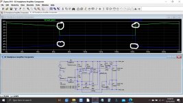
The hysteresis looks about right as it is tbh. You can see here the difference in cut-off and turn on voltages here.
The cut-off voltage should be chosen to protect the batteries. 1.1 volts per cell is probably a realistic option.
So an 8.4 volt (common value for a nominal 9V battery) PP3 has 8.4/1.2 number of cells which is 7 per pack.
7 multiplied by 1.1V is 7.7 volts or 15.4v for the two in series. So you should aim for around cut-off at say 15 to 15.4 volts, no lower or the individual cells are at risk of damage.
I think you can get nominal 9.6v PP3's as well which would have 8 cells rather than 7.
The hysteresis looks about right as it is tbh. You can see here the difference in cut-off and turn on voltages here.
Attachments
Hi all,
I have noticed that drop combo described as Rear RCA input/output:
- USB and RCA only: DAC is active, and RCA is set as output (amp is unpowered)
- Power brick and RCA only: DAC is bypassed and RCA is set as input for amp (DAC is unpowered)
- Power brick, USB, and RCA: DAC is active, RCA is set as additional input for amp
I wonder if I can use ODAC 1/8" output jack as input with disconnected USB in my DIY O2+ODAC combo? Does it affect sound quality?
Sorry for electronics nub question.
Had been looking at doing the Whammy project but right now may not be a good time to take that on for various reasons, so thinking about doing some tweaking to my O2 which has the AGDR ‘booster board’ modification (it has a thread here) which replaces the output stage.
AGDR put the booster board in for me but the mods I think I could do. My first question has to do with soldering- or, actually, desoldering. Looking through the original NwAVGuy docs, I saw the following: “Unsoldering on the board can be very difficult without professional desoldering equipment.” I don’t have professional desoldering equipment, and a quick look online suggests that such equipment would cost approximately twice as much as the amp itself. This would put the work I want to do squarely in the not-cost-effective category. I see some ‘budget’ manual solder suckers on amazon and I wonder if any of them are OK. I know how to use a wick but wonder if that would work well on the double sided PCB.
I have a little 4.5W Weller battery powered soldering iron. Before you laugh me off the site, I looked up the specs on Weller’s site and it claims a tip temp of 900° (!) Would this be workable?
Main thing I want to do is tweak the gain settings. Can somebody check my math? (Note-My O2 was modified by AGDR with the 2/3-1/3 voltage divider on the input.) Right now I have the lo-gain switch position resistors out of circuit, giving me 0.67x at the low gain setting. I want to raise that to unity (1x). Using the following formula provided by AGDR,
(1+1500/x) x 0.67= final gain
my algebra-atrophied brain returns the following gain resistor values for these gain settings:
1X = 3045Ω (3.04KΩ)
1.5x= 1.210Ω (1.21KΩ)
3x= 431Ω
Are these numbers correct? If not, what values would be correct fir these gain factors (taking the 2/3-1/3 voltage divider into account)?
Fortunately, when agdr installed my ‘booster board’, he socketed the gain setting resistor locations, so no soldering required there. I know I could probably restore the ‘stock’ gain stage values and get back a few dB of SNR, but the amp is very quiet as is and I hesitate to do too much to the board.
The Whammy is still on my radar for when the timing is right.
Sorry for the verbose post and thanks for any advice.
If I remember correctly, there isn't anything on the O2 boards that requires you to have professional equipment. Desoldering an opamp would be the most annoying thing you'd have to do, if it isn't socketed. You should be able to pull of anything using a manual solder sucker and/or some solder wick and rosin.
The opamps in the O2 are non-inverting, so they can't have a gain of less than 1. The formula is 1 + Rf/Rin.
The opamps in the O2 are non-inverting, so they can't have a gain of less than 1. The formula is 1 + Rf/Rin.
Thanks for the reply Atilla.
The way <1 overall gain is accomplished is not at the opamps; it is at the input. The input resistors can be set up to form a 1/3-2/3 voltage divider which knocks the base gain (no resistors at the Lo gain postion) to 0.67. The gain is then applied normally after the voltage divider. This is somewhere on nwavguy's blog. I couldn't locate it but here is the description given on the agdr audio site.
"The two 274 ohm input resistors on the O2 board (R3 and R7) are replaced with 4.99K resistors. The input RF filter capacitors C11 & C12 are replaced by 9pF capacitors to keep the RF filter corner frequency the same 2.6MHz. The input capacitance of the NJM2068 is assumed to be around 3pF, so the 9pF gives 12pF total. The result is forming a 1/3 / 2/3 voltage divider (2/3 passthrough, 1/3 attenuation) along with the O2's two 10K gain stage ground return resistors R14 and R20."
So this is how the 0.67 overall gain is accomplished. The R's for the Hi gain setting are set for 5.1 which gives a net 3.4 taking the voltage divider into account. I could restoree all the 'stock' parts to put the gain back where it was, but the amp is quiet now and the more 'surgery' I perform on the PCB, the more I risk ****ing something up. On the other hand, eliminating the voltage divider might make the gain stage operate more happily at the 'Hi' setting. Hmmmm....
Last edited:
Right, I see. I'm not sure why this was done. Perhaps the opamp installed isn't stable at unity-gain, and there was a need to decrease the signal level and have higher gain?
I haven't looked at mine since I boxed it in, but I'm fairly sure it is with stock values and low gain. It's been working fine since .. well, whenever that group buy was here ages ago.
At any rate, you can easily desolder resistors by simply heating and pulling the legs one at a time. Use a bit of solder wick and flux to get the remaining solder out of the via.
Last edited:
It was done because I was losing volume range on Tidal, because-get this-the volume control on the Tidal app actually applies about 6dB gain at maximum setting- in other words, it goes past unity gain and applies about 6dB or so gain at maximum, thereby leading to clipping on peaks. I discovered this after installing an app called SoundSource on my Mac. In fact, I discovered that practically everything on my system that played audio and had a volume control could do the same thing. So I individually calibrated the app volume control(s) so they wouldn't light up the clipping indicator on the loudest peaks I could find.
Downside was, now I had to wind out the volume too far on the low gain setting (effectively 0.67 with the divider). In theory at least, I should get better performance by removing the voltage divider and resetting those parts to whatever values will give me 1x (or maybe 1.5x) on the Lo input and 3-3.5x on the High input (now at 5.1 because of the divider). Basing these numbers on the volume control range I am seeing now.
I just don't trust my long-unused algebra skills. I can follow directions well though; I've built audio components from kits. When AGDR installed his 'booster board' (it has a thread here), he did the divider and socketed the gain set R's which will make them easy to fine tune. I just need to know what values need to be where. It's in the docs or this thread somewhere I assume.
Going to go ahead and restore the input parts to stock values, and then set the values for the gain resistors accordingly.
Making a couple parts upgrades suggested by agdr here:
O2 upgrades
One of his part upgrade suggestions is for D1/D2/D5/D6. If I understand in NwAvGuy's Circuit description correctly, these are only relevant to battery power, which I'm not using. Am I understanding this correctly? Thanks.
Whammy sometime in the future.
Last edited:
I can't see any reason not to link the diodes out (jumper them). It will gain you around 1.5 volts on the supply voltage and should also give a lower overall supply impedance.
You also don't need the FET's or the comparator for AC only. Jumper") the FET's and don't fit all the stuff around the comparator.
the FET's and don't fit all the stuff around the comparator.
Any physically suitable metal film resistor is fine. Just make sure they fit the board.
You also don't need the FET's or the comparator for AC only. Jumper
the FET's and don't fit all the stuff around the comparator.Any physically suitable metal film resistor is fine. Just make sure they fit the board.
- Home
- Amplifiers
- Headphone Systems
- The Objective2 (O2) Headphone Amp DIY Project