Don't replace parts 'on spec' hoping it will fix the issue... do some voltage measurements first. The resistors won't be faulty.
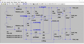
Pin 1 of U2 should be at minus 12 volts and pin 7 should be at plus 12.
Measure ALL the pins and post your results here and we'll see what is going on.
Pin 1 of U2 should be at minus 12 volts and pin 7 should be at plus 12.
Measure ALL the pins and post your results here and we'll see what is going on.
I'll just have to try and decipher that ") as it was actually this for checking the comparator voltage:
as it was actually this for checking the comparator voltage:
Hang on...
as it was actually this for checking the comparator voltage:Pins 3 and 5 are critical and if you place your meter black lead on pin 4 and measure the voltage on pins 3 and 5 you should read around plus 1.7 volts DC which is the LED forward volt drop.
Everything depends on that LED voltage as to what the comparators do.
Hang on...
So...
pins 1 and 7 which are comparator outputs are in the incorrect (rails off) state.
Pins 3 and 5 show a problem. These should be at approx minus 10 volts give or take as measured from ground. A reading of 0 volts suggests a short on those pins to ground somewhere as either the LED or resistor feeding the LED going faulty would not give 0V.
Last edited:
You need to look around pins 3 and 5. If you had 0V measuring from ground then you should be seeing something very different measuring from pin 4... yes and you are not. Are those pins floating? such as with damaged print.
Look at the circuit. The LED goes to pin 4 and so you should see the same voltage on pin 4 as on one lead of the LED.
The other lead of the LED should be approx 1.7 volts more positive. In other words you should read approx 1.7 volts across the LED and the voltage you actually measure on the LED (whether from ground or pin 4) should be the same as you see on pins 3 and 5.
Look at the circuit and it will be clear what I mean.
and you are not. Are those pins floating? such as with damaged print. Look at the circuit. The LED goes to pin 4 and so you should see the same voltage on pin 4 as on one lead of the LED.
The other lead of the LED should be approx 1.7 volts more positive. In other words you should read approx 1.7 volts across the LED and the voltage you actually measure on the LED (whether from ground or pin 4) should be the same as you see on pins 3 and 5.
Look at the circuit and it will be clear what I mean.
Well that was a fun troubleshooting experience. Cleaned up the board of flux and tidied up some solders. Studying the schematic i see your point about the LED voltage.
Found a broken trace from R6 to pin 3 on U2. Want to thank you immensely for your time in educating me! Not only saved me tonnes of time but also some cash.
One last question i cant get my head around, why when measuring accross resistors in the circuit do i record Open values?
Found a broken trace from R6 to pin 3 on U2. Want to thank you immensely for your time in educating me! Not only saved me tonnes of time but also some cash.
One last question i cant get my head around, why when measuring accross resistors in the circuit do i record Open values?
Pleased to hear you have fixed it
The resistors read open (and/or may also read lower than they should) when tested in circuit because your meter gets 'confused' by stray residual voltage (from the caps in the power supply) still appearing across those parts.
Even a millivolt or two across a resistor is enough to give an incorrect reading. In practice you can often measure lower resistor values in circuit but values in the k ohms and more need to be isolated.
Other problems when checking resistors are the circuit seeing other components in parallel with the part you want to measure and these can 'connect' via the internals of the chips and so on.
Thanks! Makes a lot more sense. A couple of anomalies ive noticed since getting the unit working.
Using headphones with gain pushed in there seems to be a crackling crunch on piano notes even at very low levels. This seems to go away entirely with S2 out. Sorry i dont currently have resistor values used in my gain circuit.
Using the unit as a preamp for some speakers, When i have the input jack grounded to chassis i can hear the ODAC input verrry faintly even when the unit is off. Upon turning on the unit there is a low hum.
Removing the ground to chassis removes audible music with unit off. Turned on the hum is gone but there is a sort of crackling ticking sound.
Is this due to simply the gain being so high for my 200w amp and 8ohm speakers?
Noises are always difficult to diagnose without actually hearing them for real. First question has to be whether these have started since you began the upgrades you mentioned earlier. If so then its a case of backtracking on the work done.
The noise related to S2 should be possible to pin down because all S2 does is alter the feedback (and so gain) around the first opamp.
I seem to remember there was comment on a known fault related to the switch ??? touching something close by. Might be worth investigating that.
The hum and grounding issues might be best approached by beginning with the unit powered by batteries and used in total isolation from anything else (just the board on its own not connected to any chassis etc) and logically build it up from that starting point and see at what points problems begin.
Removing chassis grounds should really effect anything because the audio should not be relying on that route.
Due to the O2's gain stage being up front, clipping is a function only of input level, gain setting and supply voltages - you as the user can do absolutely nothing on the amp itself that would improve matters. This is not intuitive.Using headphones with gain pushed in there seems to be a crackling crunch on piano notes even at very low levels. This seems to go away entirely with S2 out. Sorry i dont currently have resistor values used in my gain circuit.
If your high gain is 6.5X, input clipping level drops to little over 1 Vrms on AC and maybe 0.75 Vrms during battery operation.
Does the problem also occur at levels well below that? If so, either the feedback network resistors are badly misequipped (too low by at least an order of magnitude or more) or you might have a damaged gain stage opamp or another bad trace affecting one of its power pins (or the like).
If your O2 is equipped for gains of 2.5X/6.5X, I would generally advise scaling the feedback network resistors up by about a factor of 2 (while reducing the parallel capacitor by the same amount), as already suggested for the low-power version. So 3k32 instead of 1k5, 2k2/2k21 instead of 1k and 604 ohms instead of 274, with 220p being replaced by 100p of same type. Otherwise the NJM2068's output stage will break a bit of a sweat at high levels / high gain.
This is easily possible because as designed, the gain stage is insanely low noise without any good reason at all - how many sources can you name with output noise anywhere near either -122.7 dBV (20 kHz) or -121.1 dBV? (Typical DAC full-scale amplitude would be 2 Vrms = +6 dBV.) I mean, DACs with a dynamic range of 128 dB or even slightly higher do exist, but if you seriously need that, chances are your gain staging is thoroughly screwed up.
I bet you could even make the (notoriously wimpy) TL072 that failed so miserably on the master's tests work quite acceptably for the luls - with like 15k, 10k and 2k74. It still won't be perfect because even that (together with the 10k pot) provides an output stage load of about 6.4 kOhms, and you can see from measurements that it should really be around 10k, but it would be a great deal better than standard (1.5 kOhms) either way.
Hello guys and girls
I bought the DIY Desktop Kit from Head n Hifi and before I start my build (already excited) I want to clarify some things to make sure my thougts are correct. I have previous soldering experience, some DIY lamps, mechanical keyboards so this shouldn't be the biggest issue.
I guess I read almost everything on nwavguy blog.
So my plan is:
Is this correct? This is also what I read on the blog at the DIY part.
Thank you in advance.
I bought the DIY Desktop Kit from Head n Hifi and before I start my build (already excited) I want to clarify some things to make sure my thougts are correct. I have previous soldering experience, some DIY lamps, mechanical keyboards so this shouldn't be the biggest issue.
I guess I read almost everything on nwavguy blog.
So my plan is:
- I use the DIMM and measure all the parts like resistors etc.
- i.e. I see R2 on the PCB layout, check and measure the resistors, find the 220-270 ohm ones and solder them in?
- Highlight everything on the build plan (PCB layout printed out on paper)
- Solder in all the parts, make sure to follow the hints on the blog
- Test everything according to the blog
Is this correct? This is also what I read on the blog at the DIY part.
Thank you in advance.
Okay, so far I measured and marked all the resistors, yay!
What I really don't understand so far in the BOM are the gain resistors...
Do I understand that correct, that I have to choose between six possible gain resistors on R19 & R23 and three possible options on R17, R21?
I want to use the amp to power my AKG K-612 Pro, what do I use?
What I really don't understand so far in the BOM are the gain resistors...
An externally hosted image should be here but it was not working when we last tested it.
Do I understand that correct, that I have to choose between six possible gain resistors on R19 & R23 and three possible options on R17, R21?
I want to use the amp to power my AKG K-612 Pro, what do I use?
You can set whatever gain you want by choice of the feedback return resistor marked as R17 and R19 on the circuit. Leaving the resistor out gives a voltage gain of '1'. You can't go less than this.
Switch a resistor (lets say R17) into circuit and the gain follows the standard rules of:
Gain = (R16/R17) + 1
So 1k gives a voltage gain of (1500/1000) + 1 which is 2.5
Its trial and error to get the gain that suits your application best.
Switch a resistor (lets say R17) into circuit and the gain follows the standard rules of:
Gain = (R16/R17) + 1
So 1k gives a voltage gain of (1500/1000) + 1 which is 2.5
Its trial and error to get the gain that suits your application best.
Attachments
Thank you
But what means trail and error in that case? Solder in the resistors, give it a try, desolder them and solder in the next pair??
Or is there something like a recommended average? I am by no means an audiophil guy I just enjoy music and do the DIY stuff for fun and to learn something
But what means trail and error in that case? Solder in the resistors, give it a try, desolder them and solder in the next pair??
Or is there something like a recommended average? I am by no means an audiophil guy
I just enjoy music and do the DIY stuff for fun and to learn somethingNo amount of calculation and sweating over details will get you the correct value. So it really is a case of trying different values and seeing how they suit your own usage and partnering equipment and headphones.
In simple terms you want the volume control to have the right feel with regard to how loud it actually sounds.
If you only need turn it a few degrees for normal listening then you have to much gain. If you find you are turning it to 80 or 90% of maximum for normal listening then you haven't enough gain.
Thank you again for your feedback.
One last question for the moment: My AV reciever is a Yamaha RX-V365, my idea was to connect the O2 Amp to the AV receiver so that I can use the remote of the Yamaha to adjust the loudness of the O2. Does this make sense? Does this make any difference in gain settings?
Imgur: The magic of the Internet Can I use e.g. the "DVR" input?
Last edited:
- Home
- Amplifiers
- Headphone Systems
- The Objective2 (O2) Headphone Amp DIY Project