At least as good as the original!How do you find the sound of it compared to the original?
")
I don't really hear a difference, tbo., nor did I expect to hear any...
Hey guys, hoping this is the right place to post, seems too small of an issue to post a separate thread.
I've been using a plain jane o2 for over 2 years now, and its always worked great. Recently I wanted to move the input to the rear, nothing special, just a plain old 3.5mm input. I de-soldered the standard audio jack from the front (J2 pads) and went to solder my stereo jack on the P1 pads. Everything works fine, in one ear.
The first thing I thought was that the stereo jack might be bad, but if I touch the wire soldered to the hole at the front most part of the PCB to either peg on the jack, it works fine. I checked for grounds, re-soldered everything, tried different wire, and even tried using the standard holes on the J2 pads, no dice. Is there something that I'm missing? is there any way that I can troubleshoot this? I have a DMM and I'm fairly dangerous with it, I'd really just like to get my amp up and running again, even if I have to keep the input on the front. I just hope I didn't accidentally fry my amp! Any help or advice would be awesome! If you need pictures or more info just let me know, I'll get here ASAP. Feel free to hit me with any questions or "you're an idiots" that might come up.
You won't have damaged any of the opamps.
Begin by checking that no inadvertent short has been created from R7/R3 to ground. Then check continuity from R7/R3 back to your input socket.
Damage to the PCB (such as a lifted pad/crack in print) is also very likely but this is easily found and fixed and would show up in the above two checks.
Begin by checking that no inadvertent short has been created from R7/R3 to ground. Then check continuity from R7/R3 back to your input socket.
Damage to the PCB (such as a lifted pad/crack in print) is also very likely but this is easily found and fixed and would show up in the above two checks.
O2/DAC or Atom Amp?
Hi All,
First post. Amazing community here, awesome to be here. Thank you to all of you; so much knowledge and I'm humbled to be around sucha brains trust.
I've been reading lots, absorbing as much as I can and going deeper and deeper down the DIY DAC/Amp build rabbit hole.
So O2 or JDS Atom? JDS atom is way cheaper delivered, and if JDS Atom is better than it's a no-brainer, right?
Is there an equivalent of the JDS Atom + DAC combo, like the O2/ODAC combo ?
Do I need the O2+ODAC combo? Or is just the amp required? I've read heaps, but still a bit confused.
I cannot for the life of me find the build for the ODAC/Amp combo, anyone? I can only see JDs and other commercial retailers selling the O2/ODAC combo units.
Lots of questions, I know.
Cheers,
Cribey
Might also mention that JDS Atom is better in about every aspect than O2, a newer design and is also a bit better measuring. Price is on pair with O2...actually a bit lower.
Hi All,
First post. Amazing community here, awesome to be here. Thank you to all of you; so much knowledge and I'm humbled to be around sucha brains trust.
I've been reading lots, absorbing as much as I can and going deeper and deeper down the DIY DAC/Amp build rabbit hole.
So O2 or JDS Atom? JDS atom is way cheaper delivered, and if JDS Atom is better than it's a no-brainer, right?
Is there an equivalent of the JDS Atom + DAC combo, like the O2/ODAC combo ?
Do I need the O2+ODAC combo? Or is just the amp required? I've read heaps, but still a bit confused.
I cannot for the life of me find the build for the ODAC/Amp combo, anyone? I can only see JDs and other commercial retailers selling the O2/ODAC combo units.
Lots of questions, I know.
Cheers,
Cribey
Old Dynaco / AMB Upgrade to an O2 HP Amp.
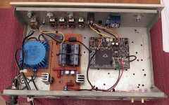
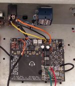
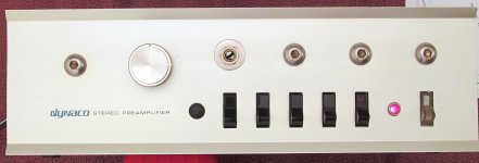
This is my 2nd O2 build, minimally utilizing just the audio portion on the board. Originally, there was an AMB headphone amp. board that was supported by the current regulated linear supply. The shell is from an old Dynaco Pat-4 preamp. The regulated supply is a standard LM317 / LM338 supply heat sinked and set to +/- 12V. The original AMB Beta 18 amp was actually quite good, but after building my 1st O2 I always seemed to prefer the it over the AMB. Purely subjective! I also traded the older Alps pot. (Radio Shack) up to a RK27. The large power supply is a little overkill for this amp. The noise floor is absolutely dead quiet. The sound is neutral and effortless with my Senn. HD580 and HD650. The RK27 pot measures and tracks well.
The turn on thump is extremely low. and verified on my scope. Much lower than NWAVGUY's shown in his measurements. The turn off thump (click) does not seem to exist at all. This might be due to the large storage of the supply and lack of bleeder resistors. The gain is set to 2.5x (1K) which is more than adequate for my needs. I use an Odac with this amp. I enjoy updating old audio with new modern electronics. I'm currently building an ESP P101 amp. around a 1980's Tandberg 3012 transformer and heat sinks.
Attachments
You won't have damaged any of the opamps.
Begin by checking that no inadvertent short has been created from R7/R3 to ground. Then check continuity from R7/R3 back to your input socket.
Damage to the PCB (such as a lifted pad/crack in print) is also very likely but this is easily found and fixed and would show up in the above two checks.
Checked for shorts, didnt see any. Re-flowed solder to make sure. Following that, I checked continuity, and for both J2 as well as P1. There is conductivity between the right side of the resistors on R3 and R7 for both channels. Still only get left channel from either lead from the jack, from both P1 and J2.
This has to be something that has gone amiss when you moved the input to the rear panel.
If you quickly link R3 and R7 with a bit of wire you should get either mono sound from both channels if there is a break somewhere or the connection will kill the audio to both if there is a short.
Try that and lets confirm that both channels on the O2 itself are basically OK.
If you quickly link R3 and R7 with a bit of wire you should get either mono sound from both channels if there is a break somewhere or the connection will kill the audio to both if there is a short.
Try that and lets confirm that both channels on the O2 itself are basically OK.
New guy
Hi, new guy here. Interested in building O2 for my college project. Already read the original blog and schematics.
Just wondering, is there any newest "official" O2 design out there. The original design I got is in 2011 (a bit outdated I guess?).
read a bit in this forum that the NJM2068 could be "better" with newer LM4562.
and by the way, could you guys tell me how the NJM2903 work in the power management, I mean to control the FET fqpf10n20c right. but on what condition did they turn on or turn off?
Thx beforehand.
The NJM2068 is an excellent device and I doubt it would be much different in sonics to the LM4562 in this application. The 4562 is also more power hungry which is always important in battery powered equipment.
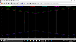
The first comparator takes an LED as an absolute voltage reference, and by comparing the supply (battery) voltage against this fixed reference allowsthe comparator to flip states when the supply voltage drops below this reference value.
R5 and R9 form a potential divider to 'scale' the supply voltage to a suitable range.
The second comparator is used as invertor to generate effectively generate the two control voltages needed for the FET,s.
When the gate of the upper FET is pulled low the FET turns on and passes the positive supply to the amp. The lower FET needs the gate pulled high to do the same.
This shows the what happens as battery voltage falls:
Attachments
The NJM2068 is an excellent device and I doubt it would be much different in sonics to the LM4562 in this application. The 4562 is also more power hungry which is always important in battery powered equipment.
The first comparator takes an LED as an absolute voltage reference, and by comparing the supply (battery) voltage against this fixed reference allowsthe comparator to flip states when the supply voltage drops below this reference value.
R5 and R9 form a potential divider to 'scale' the supply voltage to a suitable range.
The second comparator is used as invertor to generate effectively generate the two control voltages needed for the FET,s.
When the gate of the upper FET is pulled low the FET turns on and passes the positive supply to the amp. The lower FET needs the gate pulled high to do the same.
This shows the what happens as battery voltage falls:
OK, thanks for the explanation. But I still wonder why the FET's gate is connected to rail voltage via R4 & R8. Also why we have R25 as global feedback, we use them as comparator right?
R 4 and R8 are needed because the comparator has an 'open collector' output stage with no active pull-up.
Open collector - Wikipedia
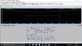
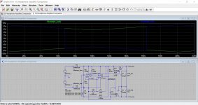
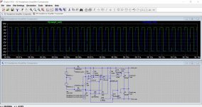
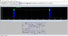
R25 add hysteresis and ensures that the output switches cleanly by slightly modifying the voltage to be sensed. As the threshold point at which the comparator will switch is approached (when the - and + inputs have identical voltages present) the output of the comparator is unstable and is massively sensitive to the slightest variation in input voltage (uV sensitive). This would mean the output passed through an indeterminate point (unstable and oscillating) and so we artificially add a little extra pull or push to the voltage being sensed by means of the high value resistor. As soon as the comparator flips state, the junction of R5/R9 is pulled a bit a lower or a bit higher depending which 'flip' the comparator is doing.
This shows the output of the two comparators in response to falling battery voltage both with and without hysteresis. You can see how noisy the switching has become. Middle image is the noise in detail.
Open collector - Wikipedia
R25 add hysteresis and ensures that the output switches cleanly by slightly modifying the voltage to be sensed. As the threshold point at which the comparator will switch is approached (when the - and + inputs have identical voltages present) the output of the comparator is unstable and is massively sensitive to the slightest variation in input voltage (uV sensitive). This would mean the output passed through an indeterminate point (unstable and oscillating) and so we artificially add a little extra pull or push to the voltage being sensed by means of the high value resistor. As soon as the comparator flips state, the junction of R5/R9 is pulled a bit a lower or a bit higher depending which 'flip' the comparator is doing.
This shows the output of the two comparators in response to falling battery voltage both with and without hysteresis. You can see how noisy the switching has become. Middle image is the noise in detail.
Attachments
R 4 and R8 are needed because the comparator has an 'open collector' output stage with no active pull-up.
Open collector - Wikipedia
R25 add hysteresis and ensures that the output switches cleanly by slightly modifying the voltage to be sensed. As the threshold point at which the comparator will switch is approached (when the - and + inputs have identical voltages present) the output of the comparator is unstable and is massively sensitive to the slightest variation in input voltage (uV sensitive). This would mean the output passed through an indeterminate point (unstable and oscillating) and so we artificially add a little extra pull or push to the voltage being sensed by means of the high value resistor. As soon as the comparator flips state, the junction of R5/R9 is pulled a bit a lower or a bit higher depending which 'flip' the comparator is doing.
This shows the output of the two comparators in response to falling battery voltage both with and without hysteresis. You can see how noisy the switching has become. Middle image is the noise in detail.
Ahh, I see. Thank you very much

I'm feeling lucky to be in this forum, that help me better understanding electronics device for audio.
Heya! Would appreciate some help if anyone would be willing.
I just finished my O2/Odac build buy I'm having a spot of trouble. All of the recommended measurements (from the NwAvGuy website) are as they should but I still can't hear anything on the output jack.
If I plug in headphones into the input jack I can hear some but I realize this is not correct behavior. From my testing the Output jack is shorted to ground but I'm not quite sure where and how to diagnose it. Any help would be much appreciated.
- Home
- Amplifiers
- Headphone Systems
- The Objective2 (O2) Headphone Amp DIY Project