Thankyou,
All I can say is WOW at the price including the PCB, think I am going to have to order this tomorrow.
Head'n'Hifi is another good option for those based in Europe.
Even better pricing. thank you for the link, don't think I could price it cheaper.
Even better pricing. thank you for the link, don't think I could price it cheaper.
Customs charges may apply within Europe as well.
Anyway, I bought from Walter from Head'n'HiFi and O2 kit was perfect, same the ODAC (I only paid customs charger for the ODAC and not for the O2 kit, don't know why).
Regards,
Raul.
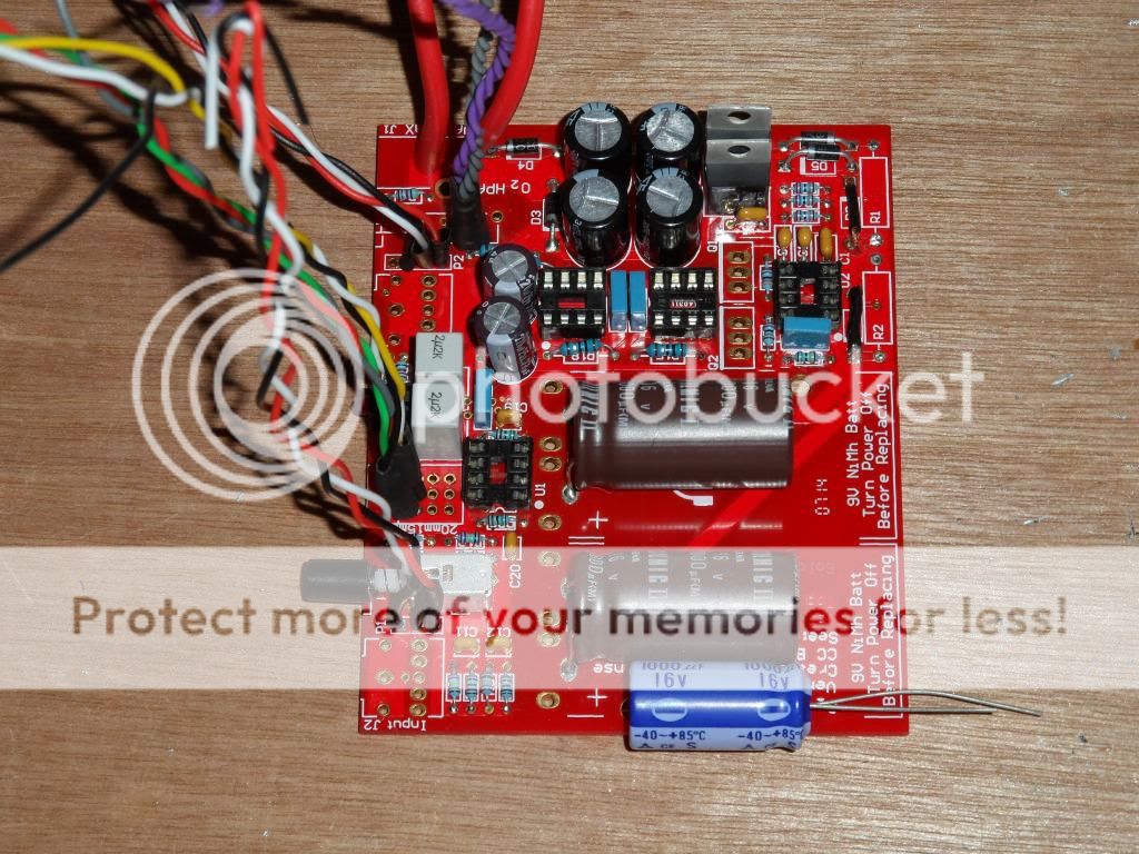
I've recently built an O2 amp as sort of an introduction to electronics and diy audio (consider me hooked  ). This headamp won't be used on the go, so I've omitted all parts related to battery operation (D2, D6, R1, R2 and the battery terminals).
A while back I came across the following thread where someone used the space this leaves to install some extra buffer caps: Desktop Objective2 Headphone Amp
E.g.:
What's your take on this? Good use of a spare electrolytic cap? Senseless overkill?
). This headamp won't be used on the go, so I've omitted all parts related to battery operation (D2, D6, R1, R2 and the battery terminals). A while back I came across the following thread where someone used the space this leaves to install some extra buffer caps: Desktop Objective2 Headphone Amp
E.g.:
What's your take on this? Good use of a spare electrolytic cap? Senseless overkill?
More a case of 'if you think it will be better then it will' I suspect. A large cap hung on the output of a 78/79 series reg does nothing to improve performance, and in some applications (probably not this one with its miniscule constant current draw) it can make things worse.
More a case of 'if you think it will be better then it will' I suspect. A large cap hung on the output of a 78/79 series reg does nothing to improve performance, and in some applications (probably not this one with its miniscule constant current draw) it can make things worse.
Fair enough, I had a sneaking suspicion that this would primarily have value as eye-candy rather than doing anything for the boards performance. Will resist the urge then.
Hi awesome DIYers!
I have an DIY O2 that was purchased used a while ago on headfi which arrived malfunctioning and showed evidence of poor build quality. I posted about it on head-fi here and got some responses saying what is probably wrong with it. Shortly after my ODAC started spewing static out of the left channel and from what I can gather it is due to an ESD damaged ES9023 IC.
So now I have 2 audiophile grade paperweights...unless I finally commit to buying a soldering iron and getting my hands dirty...which is why I'm here. By the sounds of it, I'll need to get some resistors and capacitors (the ones used for R1, R2, R16, R22, C19, C20). Actually replacing them without melting the plastic parts around them or potentially exposing ESD vulnerable components by removing resistors in the path that normally shield them concerns me. I'll also need to get any necessary extra tools to be able to remove and replace that crazy small surface mounted ES9023 IC that has 16 pins on the ODAC...
Its just all really daunting for me as a complete beginner right now. I need some hand holding to point me in the right direction with this. A soldering iron and any helpful tools you'd recommend for this and other jobs would be greatly appreciated too.
Welcome
Well this thread is all about the O2 headphone amp. If you look at the bottom of post #1 there is a link to a page I put together on faultfinding. The images in the other thread look like those 220 ohms have suffered physical damage. Close up images tend to make things look worse than they are but it does look a bit scruffy. The flux needs cleaning off to tidy it all up for starters.
You need a decent iron (sorry, I don't really know what's available at the moment, not specific models anyway) and solder braid for desoldering components.
This shows the kind of stuff I use (and how to desolder SMD)
http://www.diyaudio.com/forums/parts/127924-working-smd-how-do-without-specialised-tools.html
Welcome
Well this thread is all about the O2 headphone amp. If you look at the bottom of post #1 there is a link to a page I put together on faultfinding. The images in the other thread look like those 220 ohms have suffered physical damage. Close up images tend to make things look worse than they are but it does look a bit scruffy. The flux needs cleaning off to tidy it all up for starters.
You need a decent iron (sorry, I don't really know what's available at the moment, not specific models anyway) and solder braid for desoldering components.
This shows the kind of stuff I use (and how to desolder SMD)
http://www.diyaudio.com/forums/parts/127924-working-smd-how-do-without-specialised-tools.html
Thanks for linking me to those guides. The SMD guide really helped make me think I could handle the job. I'll do some digging to find a good soldering iron for the job and get the stuff you recommended in the guide.
Hey guys,
I have just a small question.
Is it crucial for Soundquality which kind of wire i use, to connect the back RCA's for example?
I could take wires from an old computer PSU, or from old USB-Cables(pure copper inside the wires, not the ugly fibre mix), any advice?
Thanks in advance.
I have just a small question.
Is it crucial for Soundquality which kind of wire i use, to connect the back RCA's for example?
I could take wires from an old computer PSU, or from old USB-Cables(pure copper inside the wires, not the ugly fibre mix), any advice?
Thanks in advance.
Is it crucial for Soundquality which kind of wire i use, to connect the back RCA's for example?
Type of wire "no" at audio frequencies (if you were working with RF in radio transmitter it might), but twisting them together "yes". Twist (fairly tightly, lots of twists) the signal wire with a ground wire going to each RCA jack.
Suggestion: 24AWG twisted pairs from a CAT5 ethernet cable work great, either solid or stranded.
Your RCA jack grounds should also be insulated from the metal O2 case to preserve NwAvGuy's grounding star arrangement. The case is connected to the input jack ground star while his output jack is on a different ground star segment. The Rean insulated RCA jacks are great (mouser #568-NYS367-9 for white), if you can get those 15mm diameter insulators to fit.
Last edited:
Thanks alot agdr,
will do.
Also the wire twisting wasn't shown in the "mayflower" video for example:
https://youtu.be/HGcdjAVyJnY?t=1233
Good to know how it can be improved.
And i will get all the stuff from Head'n'Hifi, so also the RCA Jacks.
will do.
Also the wire twisting wasn't shown in the "mayflower" video for example:
https://youtu.be/HGcdjAVyJnY?t=1233
Good to know how it can be improved.
And i will get all the stuff from Head'n'Hifi, so also the RCA Jacks.
awww, it's "dead".
I measured the Voltages, like "Mooly" suggested in his fault finding guide:
D3=23.1V; D4= -23.1V
and then already a problem with D1= 11,1V; D5 -11.1V instead of 11.5 to 12V
with U2 installed:
pin 4 of U1, U3, 4 = -2.9V
pin 8 = 0V
So i guess i can already order new parts for Q1 and Q2?
I measured the Voltages, like "Mooly" suggested in his fault finding guide:
D3=23.1V; D4= -23.1V
and then already a problem with D1= 11,1V; D5 -11.1V instead of 11.5 to 12V
with U2 installed:
pin 4 of U1, U3, 4 = -2.9V
pin 8 = 0V
So i guess i can already order new parts for Q1 and Q2?
- Home
- Amplifiers
- Headphone Systems
- The Objective2 (O2) Headphone Amp DIY Project