OK, so this is kind of my question. I had assumed that the reference voltage of the LED was only important for battery operation and not AC input. Is this not the case? The closest I have to the BOM LED is a 1.7V red LED, can I clarify that the O2 will not operate with the LED at a different voltage?
If the LED voltage is grossly incorrect then it could cause the comparator (U2) to shut the rails off when AC powered. Very unlikely but possible non the less.
Did you run through the test procedure I linked to ? That would show up any problem with the power supplies.
I've run through the tests now, seems that I'm just above or below the expected range for each test:
16V at D3
-15V at D4
10V at D1
-10V at D5
-10V at pin 4 and +10 at pin 8 for U3 and U4
I have also just noticed that U3 is very hot when I turn the amp on, so something is definitely wrong. Any ideas? and are those voltages close enough to the expected range? I'm running off a 12VAC supply, which is obviously at the lower end of the power requirement
Those voltages are low but if U3 is running hot then that means its pulling excess current which is going to have the effect of lowering the rails anyway as it is pulling the input to the regulators down.
First thing to do is simply remove U3 at this stage.
If there was a short on the output pins of U3 (pins 1 and 7) then that could cause it to run hot. Make sure there are no solder blobs shorting any of the pins on that opamp.
With U3 removed, check the voltages on all the pins of U3's socket.
Only pins 4 and 8 should have any voltage present (-/+ 11.5 volts or so)
That's pretty much conclusive proof the opamp is faulty in some way. Have the 12 volt rails come back to their correct values with U3 removed ?
With the faulty opamp removed the circuit should now work normally and produce audio on one channel. For test purposes you can substitute the faulty opamp with most common dual opamp types such as a 4558, TL072, NE5532 etc as a test.
With the faulty opamp removed the circuit should now work normally and produce audio on one channel. For test purposes you can substitute the faulty opamp with most common dual opamp types such as a 4558, TL072, NE5532 etc as a test.
Finally got around with doing the measurements on my broken O2.
One of the 4556AD had died, it was outputting high voltages from pin1 while the other 4556AD was working properly (very low voltages). I also switched them around to confirm it.
Now I need to find a shop that sells them, Partco doesn't have them and elsewhere the shipping costs are around 10€.
Ebay here I come? Or I'll give up searching and just order them from Head 'n' HiFi.
I try my first diy o2 today (first project) , I know nothing about electronic , although I did check the resistor as nwavguy told .
o2%2520resistances%2520no%2520power%255B3%255D.png (image)
My R25 is 390k far from 330k
and all my R10 R11 R15 R18 is all 1.2ohm (the resistor off board also 1.2ohm , I bought all 1ohm 1%)
Is there a problem with my board ? please help
o2%2520resistances%2520no%2520power%255B3%255D.png (image)
My R25 is 390k far from 330k
and all my R10 R11 R15 R18 is all 1.2ohm (the resistor off board also 1.2ohm , I bought all 1ohm 1%)
Is there a problem with my board ? please help
I need help with finding a fault. I've bought a brand new O2 amp. It works fine when connected to a power source. But the batteries are not charging and therefore I can't use it without a power source. However the 9v batteries do work when I remove them and charge them in a separate battery charger unit I own - which is not convenient!
Rather than sending it back to Switzerland for repairs, which will cost me money and incur a two week or more long wait. I've decided to take out my test probs and soldering kit. Does anyone where exactly I should be looking on the circuit to troubleshoot for a solution the fault?
Rather than sending it back to Switzerland for repairs, which will cost me money and incur a two week or more long wait. I've decided to take out my test probs and soldering kit. Does anyone where exactly I should be looking on the circuit to troubleshoot for a solution the fault?
Does anyone where exactly I should be looking on the circuit to troubleshoot for a solution the fault?
Mooly's fault-finding guide in the post #4652 above is a great place to start, then post the results. A high resolution picture (or any picture!) of the front and back would be extremely helpful too. In fact, for this particular thing, I wouldn't be surprised if the picture does it.
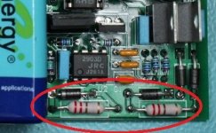
The two large resistors in the red circle in the photo below are the entire battery charging circuit.
") They supply a trickle charge from the AC supply to the batteries. Those two diodes in the circle allow power to flow from the batteries, so make sure your similar two diodes have the band in the same direction as those in the picture.
They supply a trickle charge from the AC supply to the batteries. Those two diodes in the circle allow power to flow from the batteries, so make sure your similar two diodes have the band in the same direction as those in the picture.So since yours isn't working... the other thing I've seen folks do is get the polarity of the battery terminals that are soldered into the PC board reversed. In the bigger picture you can barely see the correct way. The large battery terminal on the left battery PC board terminal goes next to the left edge of thc PC board. That mates up with the positive (+) marking on the battery and the smaller terminal on the battery. Same for the other set of battery terminals. If your battery has negative (-) closest to the else of the PC board your terminals are swapped. If the battery polarity is reversed like that they won't charge. If you have done this some solder wick will easily remove the solder on those PC battery terminals - the holes are large - and they will just drop right out onto the floor if you have the board upside down.
It is also entirely possible for those Tenergy 9V batteries to short internally (I've had two do it so far) or be open (I've had one of those). But since you say the batteries work in other devices that probably isn't the problem. When they short the battery case puffs up a bit in the middle.
And yet another thing that can happen is the battery terminals not making contact once the battery is snapped in. I've had this happen before. If you can wiggle the battery back and forth easily when it is intsalled that might be the issue. To correct that gently squeze two of the clip "petals" (the larger 9V terminal) to move them in a bit and try it again with the battery.
Attachments
Last edited:
Specified for use with primary (non rechargeable) rather than secondary batteries maybe. Primary types would go pop if you attempted to charge them.
They are definitely of the rechargeable variety - 9v NI-MH 300mAh. I guess he just forgot to put those resistors in when he was building it.
Do you think the soldering on the under side looks clean?
Hi all, just come across this amp, and it sounds like it is what I need.
Few questions, does anyone know if you can buy it in kit form? As I would like to use my own case.
If it is not available in kit form, has anyone from the UK built one, and how much were the parts excluding PCB, case and wall wart. Don't really want to spend a night on RS or Mouser lol.
Few questions, does anyone know if you can buy it in kit form? As I would like to use my own case.
If it is not available in kit form, has anyone from the UK built one, and how much were the parts excluding PCB, case and wall wart. Don't really want to spend a night on RS or Mouser lol.
- Home
- Amplifiers
- Headphone Systems
- The Objective2 (O2) Headphone Amp DIY Project