even if LME's output is not connected to PCB (when configured to be on-adapter unity gain)?
however if output is not connected in such configuration it... still connected to ground via 'gain switch' and its resistor and to VR - via on-board NFB. However, do you have that switch and what resistor is connecting NFB to ground in your device?
What would I do in such situation - I would create small board instead of adapter that would have own ground and all required power bypassing caps + own NFB resistors. But its quite a lot amount of work without guarantee since reason is not known exactly yet. Actually possible reasons as I can guess are
1) 'Power management' unit self oscillation due to overcurrent
2) Inproper power rails bypass. Capacitors must be close to power pins and their ground connection points must be near to NFB connection point.
3) Too capacitive load for LME. Even if in unity-gain config having output connected to NFB only. Thats quite a strange, but still possible.
Last edited:
...Than add here BUF634 or LME49600 at output - and here is new amp )I would create small board instead of adapter that would have own ground and all required power bypassing caps + own NFB resistors
The thing is interesting: is the LME49990 is unable to drive the volume pot ?!
Fancy fast opamps require careful frequency bypassing/compensation that are not met in O2 cuz its not designed for such opamp:
1) Power bypassing recommendation that given in LME's datasheet: 'To achieve a low noise and high-speed audio performance, power supply bypassing is extremely important. Applying multiple bypass capacitors is highly recommended. From experiment results, a 10μF tantalum, 2.2μF ceramic, and a 0.47μF ceramic work well. All bypass capacitors leads should be very short. The ground leads of capacitors should also be separated to reduce the inductance to ground. To obtain the best result, a large
ground plane layout technique is recommended and it was applied in the LME49990 evaluation board'
2) About frequency compensation. Fast opamps can amplify up to tens of MHz. At such frequencies inductance of few cm wire loop can be enough to cause phase shift enough to turn NFB into PFB. So frequency compensation capacitors better be placed at millimeters distance from such opamp's pins.
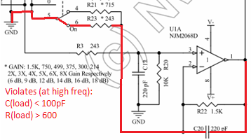
3) Load (even if its a pot) may have stray capacitance, enough to slowdown output that again will lead to critical phase shift. Datasheet tells that at unity gain config such capacitance is 100pF. It would be so if wire of 1..2m length was connected to your opamp's output and unlikely that small pot will have such capacitance.. But who knows..")
4) There is also one suspicious moment in the circuit: NFB's ground resistor have two possible values - 243 or 715 Ohm depending on switch position/presence. Whats yours? Suspision its because frequency compensation cap via 243 Ohm resistor can again cause problems, but its most unlikely guess cuz even 243Ohm resistor must be enough to avoid such problems.
1) Power bypassing recommendation that given in LME's datasheet: 'To achieve a low noise and high-speed audio performance, power supply bypassing is extremely important. Applying multiple bypass capacitors is highly recommended. From experiment results, a 10μF tantalum, 2.2μF ceramic, and a 0.47μF ceramic work well. All bypass capacitors leads should be very short. The ground leads of capacitors should also be separated to reduce the inductance to ground. To obtain the best result, a large
ground plane layout technique is recommended and it was applied in the LME49990 evaluation board'
2) About frequency compensation. Fast opamps can amplify up to tens of MHz. At such frequencies inductance of few cm wire loop can be enough to cause phase shift enough to turn NFB into PFB. So frequency compensation capacitors better be placed at millimeters distance from such opamp's pins.
3) Load (even if its a pot) may have stray capacitance, enough to slowdown output that again will lead to critical phase shift. Datasheet tells that at unity gain config such capacitance is 100pF. It would be so if wire of 1..2m length was connected to your opamp's output and unlikely that small pot will have such capacitance.. But who knows..
4) There is also one suspicious moment in the circuit: NFB's ground resistor have two possible values - 243 or 715 Ohm depending on switch position/presence. Whats yours? Suspision its because frequency compensation cap via 243 Ohm resistor can again cause problems, but its most unlikely guess cuz even 243Ohm resistor must be enough to avoid such problems.
hmhmhm. can you build a unity gain buffer on the adapter and do not connect to main board both ouput AND negative input pins?
As I remember from you experiments - when output not connected - its still oscillated together with 4556. However I can guess that negative input was still connected that meant output of opamp also was connected to board via negative input pin.
As I remember from you experiments - when output not connected - its still oscillated together with 4556. However I can guess that negative input was still connected that meant output of opamp also was connected to board via negative input pin.
Here is another interesting result. I changed C19 C20 from 220pF to 20pF. The result:
LME49990 - clean output.
But it is depending on where I taking the ground point.
If ground is taken on the input jack: LME's output clean, but there are oscillations after 4556.
If ground is taken on the output jack: LME's output clean, 4556 output clean (small noise).
If the ground taken on the battery mid point: LME - oscillation, output 4556 - small noise.
That noise (on phones jack ground and output) measures as follows:
Amplitude - 2..12milli Volt (mostly 2-5mV)
RMS - 15...18 millivolt
Pk-Pk 22...46 millivolt.
so.. inappropriate PCB layout (some ground loops inductance) + too capacitive load via NFB'c capacitor - ground resistor.. Fast good opamps require good care to work correctly.
I don't want to scare you but.. making amplifier to be quiet without input signal is only half of work.
Then you have to check how it behaves with different loads with different input signals: sine and especially square pulses with different levels. Its common situation when stable in silence amp generates some crazy signal under some specific conditions..
Last edited:
Of course. But there is a big problem - I don't have good signal source. There is Creative Audigy ZX soundcard in my PC only. The step I can to preform is to switch it to 196KHz sampling rate, than to use some software generator. I'll be able to feed signals up to about 90KHz sine, and possible up to 40-60KHz square.Then you have to check how it behaves with different loads with different input signals
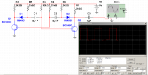
I tried to run some simulations. Unfortunately there is no pspice model of the LME49990 that compatible with Proteus VSM (looks like it use SPICE3F5), so I used similar opamp - AD797.
From my research I found that best attenuation at 90 - 100MHz area is acquired with small: 10-20pF caps, + 100-120Ohm resistor in NFB network, or just without any caps here.
So I removed C19 and C20. The oscillations completely gone from everywhere. The amplitude of the residual noise is about 2-10mV on the opamp output @ full bandwith, with bandwith limited to 20MHz there is flat line on LME and NJM4556 outputs. More testing when I'll get the load resistor set.
Only good square pulses will tell if capacity in NFB is ok. Squares must be square, without overshoots.
As about low resistance to ground in NFB, see:
However usually (with less... cool opamps) putting serial resistor of>= 100R is enough to compensate any capacitive load, but since its a really cool opamp even 200 Ohm may not do the trick here..
As about low resistance to ground in NFB, see:
However usually (with less... cool opamps) putting serial resistor of>= 100R is enough to compensate any capacitive load, but since its a really cool opamp even 200 Ohm may not do the trick here..
Attachments

I wonted to check the square wave behaviour, and started from the test of my PC output... The "godlike hi fidelity" SoundBlaster Audigy ZX overshot even at 1 KHz  At higher frequency's, everything so bad, that shame to show the plot
May be an issue with the cable capacitance I use 1.5m custom made interconnect produced from the hi quality microphone cable...
At higher frequency's, everything so bad, that shame to show the plot May be an issue with the cable capacitance
I use 1.5m custom made interconnect produced from the hi quality microphone cable...Actually it's much simpler than that. You cannot use a soundcard to generate good square waves, full stop. Square waves have harmonics basically extending to infinity, requiring high bandwidth for good fidelity. Now digital audio is inherently limited to fs/2, abs max, and will use steep interpolation (for D/A) and anti-alias (for A/D) lowpass filters, as required to satisfy the Nyquist criterion. With a maximum 192 kHz sample rate, you're limited to <96 kHz, which probably means any square waves beyond low single-digit kHz won't be looking very good. Even less so at 44.1 or 48 kHz.
What you want to be doing with a square wave test is inspect frequency response well into the MHz range. Which obviously won't work under these circumstances. It takes a proper square wave generator of some kind and a scope of half-decent bandwidth (like at least 20 MHz analog, with a digital scope needing to sample at >~60 MSps to match that).
If a soundcard could in fact be used to generate good square waves, it would be bad at its actual job, as it would leave aliasing signals essentially unfiltered. Loud ultrasonic components are not especially well-liked among audio amplifiers, especially those of highish HF IMD.
hello sgrossklass ,
Thank you for you input. I know the importance of the measurement tools. I have no problem with the scope: my Tektronix THS720A 100MHz 500MSp/s is very good for DIY purposes. Now the generator. I think to get one to use as source for THD analyzer too.
But all available multi function generators are not meet low THD requirement .
So I'll be happy to see you suggestion about ASG. Below is what I found on the Ebay. Are those any good ?
TAG101 Audio Generator Function Signal 10 to 1MHz | eBay
New Digital Function Signal Generator 0 1Hz 2MHz Audio | eBay
- Home
- Amplifiers
- Headphone Systems
- The Objective2 (O2) Headphone Amp DIY Project