I doubt you would gain anything from going larger... and there are real downsides too such as increased "copper losses" within the small transformer as the rectifiers conduct 'harder' but for less time. A 1000uf (which is what you have now, 2 times 470uf) per rail is plenty for a few tens of milliamps current draw.
Couldn't comment on the enclosure question.
Couldn't comment on the enclosure question.
This looks like the place to post as I'm about to build my own O₂ amp, sorry if I'm wrong.
I'm pretty excited. I've made two cmoy's, a Linkwitz crossfeed, and a minty boost, so I think I've got the soldering skills; though sadly I feel like my understanding of circuits isn't as great as I'd like.
Getting the pcb, enclosure, and machined front plate from JDS; everything else from Mouser.
So my questions:
In his articles NwAvGuy seemed pretty adamant about the parts as is, since that's what he's done the full bore measuring on. That said, this agdr person seems pretty competent and still posts here. Are the "modern upgrades" here generally accepted as a good idea? How about the "lower Johnson noise" mod?
I noticed that the LED is "not recommended for new designs". Should I care? If so, is there an alternative that fulfills the same purpose?
The default pushbutton switches are backordered and won't be in for nearly two months. The alternate is in stock, it's the "shorting" version of the same thing. Is there anything I should be aware of using these?
A couple of the resistors are back-ordered too. Is it worth waiting a week to get the Vishay ones, or are the Xicon alternatives completely comparable? I was wondering since the data sheets on the Vishay resistors specifically say low noise.
Thanks in advance for any help!
I doubt you would gain anything from going larger... and there are real downsides too such as increased "copper losses" within the small transformer as the rectifiers conduct 'harder' but for less time. A 1000uf (which is what you have now, 2 times 470uf) per rail is plenty for a few tens of milliamps current draw.
I'm planning on a C-L-C filter eg cut the traces and add some inductors in between the supply caps.
I'm planning on a C-L-C filter eg cut the traces and add some inductors in between the supply caps.
I don't really think you will gain anything tbh. Don't let that stop you trying it though.
Are the "modern upgrades" here generally accepted as a good idea?
Welcome to the forum!
")
Those part "upgrades" are primarily tightening up specifications on the parts (tolerances) without changing their values (capacitance, resistance, or voltage ratings). In the 3 years since the O2's BOM was released those specifications "upgrades" can be made for little or no cost in many cases. The list was just a result of me going out to get the parts once on NwAvGuy's BOM to build some boards, then realizing I could do a lot better these days on specs that what he had originally listed back in the day.
Most of those "upgrade" parts are not in the signal path, like the C16 & C21 timing capacitors on the mosfets that control the power management switching on and off. The originals were Z5U dielectric and 20%, while the "upgrade" is COG (not sensitive to applied voltage or temperature) and 5% - at just $0.28 more. Three people have emailed me now saying that particular "upgrade" fixed the turn/on turn/off thumps they were getting in the O2's.
The change just went to a much tighter tolerance for the caps, which in turn would help the two mosfets switch at closer to the same instant. Switching at different times leaves one power rail "up" while the other is "down".The one "upgrade" that is in the signal path is that C8/C9 change from 220uF to 330uF. NwAvGuy made a comment in his blog saying "don't increase the value of this cap". I think the problem was related to how fast the power rails drop once the mosfets switch off, but it could be something THD+N related he was seeing on his dScope tester. At any rate if you might want to skip that one if you want to be 100% sure none of the upgrades have an effect on specifications. I've been meaning to add a note about that.
Same with the "lower Johnson noise" modification. I have a separate list of modifications posted. I kept it separate since those are things that may very well have an effect on specifications (better or worse) and until tested with a dScope or AP, which they are not yet. The mods are all based on datasheet numbers and the math. Stay away from the modifications if you want to be 100% sure you are not messing with NwAvGuy's measured numbers.
I bought a bunch of those O2 switches a while back and they are yours at-cost, whatever mouser is selling them for plus actual shipping cost, just send me a PM on the forum here if you want.
As long as you can still buy the BOM LED you would be best using it since it sets the voltage reference for the power management comparator. The manufacturer is probably just changing over to some new design.
Last edited:
...also looks like Digikey and onlinecomponents.com have that O2 switch in stock. At Digikey it is #CKN1191-ND and at onlinecomponents.com #PN22SJNA03QE.
The LED is a bigger problem. Mouser still has them, but only Arrow and Future Electronics have some stock. It does look like Everlight has discontinued the part. It may be necessary to eventually pick a new red led and make a front panel change when they finally go out of stock. Of course it is always possible just to glue a T3 red LED in the hole then run leads down to the board.
The LED is a bigger problem. Mouser still has them, but only Arrow and Future Electronics have some stock. It does look like Everlight has discontinued the part. It may be necessary to eventually pick a new red led and make a front panel change when they finally go out of stock. Of course it is always possible just to glue a T3 red LED in the hole then run leads down to the board.
Thank you for the reply!
I think I'll go ahead and make the non-signal path upgrades and avoid the rest.
Plenty of time to go really "off-script" in the future when I made a dedicated ODA type thing (perhaps with your design).
In that light, I think I'll also get the back-ordered resistors and wait on them.
Thank you for the offer of the buttons. Perhaps I'll take you up on that. Though Digi-key only wants 3$ to ship them to Oregon in regular mail.
I tried to figure out what the difference was with the versions that are in stock with Mouser.
If I'm understanding the schematic and the difference between make-before-break and break-before-make correctly (and I'm well aware I may not be), the power switch to "off" just goes to nothing, so the timing of breaking the circuit doesn't matter; and the gain switch being make-before-break means that in the middle of switching, the gain resistors would briefly run parallel, giving much higher gain (~8x I think*), instead of the circuit being broken during the switch. Which seems like a potential issue, but not a fatal one.
(*my numbers with default R17 and R19 in parallel: (1/1000Ω + 1/274Ω)^-1 = ~215Ω; gain = 1+1500Ω/215Ω = ~8)
I looked into the possibility of getting the entire order from Digi-Key or Online Components, but they're both missing a few things (Online Components quite a few).
(PS: is it just me or are the BOM importers on these sites kind of rubbish?)
Jingu - you are exactly right about the shorting switches and what would happen. NwAvGuy isn't using 1/2 the power switch so no issue there, but yep you would get a momentary gain boost with the gain switch, which would probably get annoying if you used it a lot.
At $3 shipping might as well go with Digikey! If you get a bad switch they will send you another no charge (same with Mouser, at least here in the states), plus they probably do have a few of the other parts.
I've only tried the BOM importer at Mouser. I eventually got it to (mostly) work, but it took quite a bit of massaging. A dozen or more parts had to be hand-picked from some similar-looking manufacturer part numbers.
On the resistors, the lower current noise versions may have just a tiny bit less (current) noise, but in reality although it might be measureable with sensitive equipment the improvement probably wouldn't be audible. That is assuming all the resistors are metal film here, and not carbon film. So the one resistor I posted as an "upgrade" is really more of a "do it because you can and its cheap" thing than something I would expect to actually produce any audible improvement. BTW - that resistor is only available at Digikey though, so if you are placing an order anyway...
Somewhere along the way - this thread, his blog - NwAvGuy in the first few weeks of the O2 mentioned he had originally specifed the Vishay RN (if I'm remembering that prefix right) "military" low noise resistors but discovered from his dScope measurements it didn't make any significant noise difference when he replaced them with the much cheaper Xicons.
Last edited:
I'm planning on doing the O2 build with the ODAC and I've got a few questions that searching this thread can't answer (maybe I'm not good with coming up with the right keywords).
First, are the battery terminals necessary with the ODAC? NwAvGuy said that they made a convenient backstop for plugging in the USB, but are the necessary with using the mounting screws?
Second, is there a part number for the fully insulated DC connector? I like the idea of putting the power in the back.
To the engineers around here!:
Having built a low power version of the O2 with the OPA2277/TLE2062 combo, the recommended changes to gain resistors, compensation caps and output resistors, I was wondering what would happen if I decided to swap the op amps back to the "original" ones without changing the other components back.
Would there be any measurable objectionable differences (let alone audible ones) compared to an "stock" O2 with the 2068/4556?
I know the output impedance would be about 3.2 ohms instead of 0.5, but the hphones I use are Beyers DT-250 80 ohms and DT-770 250 ohms so I guess no big issue there?
I'm planning on doing the O2 build with the ODAC and I've got a few questions that searching this thread can't answer (maybe I'm not good with coming up with the right keywords).
First, are the battery terminals necessary with the ODAC? NwAvGuy said that they made a convenient backstop for plugging in the USB, but are the necessary with using the mounting screws?
First: I would say yes, they are a good mechanical backstop when plugging in the usb and the jack (if you choose to mount it). The mounting screw is not so much a mounting screw, but rather an alignment screw. In fact some vendors of the kit include nylon versions of the screw and nut, which I think are kinder on the PCB:s. Less risk of damaging the PCB:s by overtightening.
But you could definitely do with only one battery terminal, that would provide enough strength and still look less crowded. Check my photos a on this post
to see what a stuffed up O2 looks like!
Second: some vendors sell bits and parts for the O2, check JDS labs!
Good luck!
Last edited:
Hello,
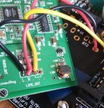
I just assembled my O2 + ODAC and when i was about to install everything into the case my thumb touched the "coil" on the ODAC and the top of the coil broke in two. Everything still works but I'm wondering if there might be some consequences?
See attached pictures.
I just assembled my O2 + ODAC and when i was about to install everything into the case my thumb touched the "coil" on the ODAC and the top of the coil broke in two. Everything still works but I'm wondering if there might be some consequences?
See attached pictures.
Attachments

Hello,
I just assembled my O2 + ODAC and when i was about to install everything into the case my thumb touched the "coil" on the ODAC and the top of the coil broke in two. Everything still works but I'm wondering if there might be some consequences?
See attached pictures.
It's an unshield inductor. Doubt it would affect much.
Gain setting question:
I just purchased an O2 kit from HeadnHifi (wonderful customer service) and have a question about the standard gain setting. I don't have electrical engineering background but in learning how to read diagrams and doing some basic calculations I wanted to confirm the gain settings and calculations the was standard on the unit.
I currently run a pair o AKG702 and Philips X2 on these and would like to lower the gain a bit if possible and/or recommended. I've read some articles discussing this but didn't see anything specific to the resistors to use.
Currently:
R16, R22= 1.5k
R3,R7, R19, R23 = 274
R17, R23 = 1k
So.....
If gain switched to R17,R21 path, this gives me 2.5x gain (1+1.5)
If gain switched to R19,R23 path, this gives me 1x, i.e. unity gain (1+0)
Is that correct?
Thanks in advance for any help.
Last edited:
This explains the gain calculations, post #4020
http://www.diyaudio.com/forums/head...o2-headphone-amp-diy-project.html#post3988791
The gain is (R16+R19)/R19 so that gives a gain of 6.5 (the high gain setting). For unity gain you would need to remove either R17 or 19, that switch position then giving a gain of 1.
I'm not sure thats the best approach tbh, or lets just say without testing fully. I suspect for unity gain then the best approach would be to link out R16 (short it out).
You might find a better approach is to increase R7, the input resistor. Making that 10k would automatically halve the signal applied to the 02.
Its always trial and error when it comes to gain, to get something that feels and sounds right in relation to volume setting.
This explains the gain calculations, post #4020
http://www.diyaudio.com/forums/head...o2-headphone-amp-diy-project.html#post3988791
The gain is (R16+R19)/R19 so that gives a gain of 6.5 (the high gain setting). For unity gain you would need to remove either R17 or 19, that switch position then giving a gain of 1.
I'm not sure thats the best approach tbh, or lets just say without testing fully. I suspect for unity gain then the best approach would be to link out R16 (short it out).
You might find a better approach is to increase R7, the input resistor. Making that 10k would automatically halve the signal applied to the 02.
Its always trial and error when it comes to gain, to get something that feels and sounds right in relation to volume setting.
Thanks Mooly....so what you're saying is my calculations are just waaaayyyyy off
So if do my math correctly, the current setting for gain is 2.5x and 6.5x switching between R17 and R19.
So after reading your post referenced above, I could theoretically remove R19 and R23 which would give me unity gain when switched and keep R17 and R23 at 1k for the 2.5x. I did inquire from HeadnHifi and Stefan responded as such but I wanted to understand the reason behind this as well as allow me to play with gain in the future.
That's it (you mean keep R21) You can't damage anything altering these resistors, you will just have to try the different gains and settle on what works best. I know that sounds unscientific but its just not possible to calculate the gain you need for your headphones.
Its try it and see.
(you mean keep R21) You can't damage anything altering these resistors, you will just have to try the different gains and settle on what works best. I know that sounds unscientific but its just not possible to calculate the gain you need for your headphones. Its try it and see.
- Home
- Amplifiers
- Headphone Systems
- The Objective2 (O2) Headphone Amp DIY Project