UnKnown,
Thanks for the information on the change of components. Without reading through the entire thread I will assume this was to address some issue found later in the build. I;ll tell m daughter to replace those parts that she already bought and put in the new values.
Steven
Thanks for the information on the change of components. Without reading through the entire thread I will assume this was to address some issue found later in the build. I;ll tell m daughter to replace those parts that she already bought and put in the new values.
Steven
The component change can be seen in the latest BOM (excel file on NwAvGuy page, Dec. 2011). The PDF Documentation package has a slightly older BOM.
C6 and C7 are not critical and the 220nf film caps will work fine. He changed the cap values because the National Lm7912 datasheet says a 1uF cap is required on the output. Usually the output cap on LM7812 and 7912 is considered optional.
C6 and C7 are not critical and the 220nf film caps will work fine. He changed the cap values because the National Lm7912 datasheet says a 1uF cap is required on the output. Usually the output cap on LM7812 and 7912 is considered optional.
UnKnown,
Thanks for the followup explanation. I zoomed in on the pdf and could see some of the positions more clearly by the drawing of the devices but I'm not clear on the way that the 8 leg op amps are supposed to go. There is a dot in one corner of the device on the drawing and another off from the opposite corner, which one would be the #1 lead, I would assume that would be the dot in the corner but haven't look that hard yet at the schematic and the layout to see how they match up? I also see a notch shown on the opamp drawings, would that be on the #1 side of the opamp?
Thanks for the followup explanation. I zoomed in on the pdf and could see some of the positions more clearly by the drawing of the devices but I'm not clear on the way that the 8 leg op amps are supposed to go. There is a dot in one corner of the device on the drawing and another off from the opposite corner, which one would be the #1 lead, I would assume that would be the dot in the corner but haven't look that hard yet at the schematic and the layout to see how they match up? I also see a notch shown on the opamp drawings, would that be on the #1 side of the opamp?
All the grey dots are holes in the PCB, either for component leads or just to connect traces on the top and bottom layer of the board. ")
The DIP8 components (U1-U4) (and their sockets) are placed like shown on the drawing. You can see a small notch at one end of them on the drawing. Many opamps have this notch but these have a dot in one corner instead of the notch at one end. Opamps are marked with either a notch, a dot or both, so the dot on the opamp goes where the notch on the drawing / PCB is.
The DIP8 components (U1-U4) (and their sockets) are placed like shown on the drawing. You can see a small notch at one end of them on the drawing. Many opamps have this notch but these have a dot in one corner instead of the notch at one end. Opamps are marked with either a notch, a dot or both, so the dot on the opamp goes where the notch on the drawing / PCB is.
You need to backtrack and check the voltage firstly at the 7812 input which should be 15volts or more for the reg to work.
What is 7812? - how is it marked on pcb?
U5 and U6 at the very beginning of the input to the AC input circuit. You can see the 7812 and 7912 there after the first diodes and capacitors in the AC input circuit.
Indeed, thanks!
You need to backtrack and check the voltage firstly at the 7812 input which should be 15volts or more for the reg to work. The voltage on pin 3 (output) should be +12 volts.
So which pin of U5 should have 15V - the one closest to C5? And I'm confused by pin3 +12V: are you still talking about U2 pin or about U5?
co2,
If I am following this correctly on U5 pin #1 is the input and should be a minimum of 15V and pin #3 is the output of that same regulator and should show a voltage drop to 12V. As you look at the front of the regulator pin #1 should be on the left hand side and pin 3 on the right. Hope that helps. I assume the same holds true for the U6 regulator also but you are rectifying so one is the + side of the circuit and the other is the - side for your positive and negative power legs.
If I am following this correctly on U5 pin #1 is the input and should be a minimum of 15V and pin #3 is the output of that same regulator and should show a voltage drop to 12V. As you look at the front of the regulator pin #1 should be on the left hand side and pin 3 on the right. Hope that helps. I assume the same holds true for the U6 regulator also but you are rectifying so one is the + side of the circuit and the other is the - side for your positive and negative power legs.
What is 7812? - how is it marked on pcb?
Kindhorman has pointed you in the right direction
(just measure the voltage on the three pins. The middle one should be zero, one of the end pin should have more than +15 volts present and the other end pin should have approximately +12 volts. As I mentioned earlier, the +12 volts should be present on both sides of D1. That D1 voltage is really all you need measure to confirm or otherwise that the regulator is working)
Thanks again Mooly,
I only looked at one of the data sheets so I didn't see the different pin designations. This will all help me to help my daughter make this board work. She should enjoy it and learn a lot from building it.
You're welcome
(and if you haven't already seen it, there is a link in post #1 to a fault finding guide that I put together in response to all the questions being asked on this design)
It certainly looks that way. Two things to bear in mind though, although its 99% certain that the reg is duff.
Firstly, are you measuring on the pins themselves or on the PCB. If on the pins then there is no doubt with the readings. If on the PCB then any open circuit print could give a misleading result.
Secondly, and very unlikely... make sure there isn't a near short on the regulator output. Some regs can sense that and go into a "foldback current limit". If the regulator is cold and you can't measure a short to the zero volt line (measure with it off), then the regulator is faulty.
Just completed my O2 build and need some help. My issue is that amp works but is quieter than it should be. Both channels are the same. For example with my headphones plugged straight into my cell phone I start playing music at a normal level. I then plug the headphones into the amp, connect the cell phone to the amp, set gain to low (2.5x) and turn the amp's volume all the way up. In theory the headphones should be getting 2.5x the power right? Instead the music is quieter than directly connected to the cell phone. Max volume on the O2 is reducing the volume compared to directly connecting. Same thing on various sources. Setting high gain raises the volume but it is still much quieter than it should be.
I ran through all the tests on the blog and everything was normal except that pin 2 on U2 is -8.9v instead of -8.4v. This is with only U2 installed, no batteries, and power turned on. Is that a clue?
Only U2 installed, no batteries, and power turned on:
U2 pin1: -11.83
pin2: -8.90
pin3: -10.16
pin4: -11.84
pin5: -10.16
pin6: -11.83
pin7: +8.42
pin8: +11.78
The side of R5 closest to the batteries is +11.78 and the right side of R9 closest to C6 is -11.85 which are both right according to the blog. I've checked carefully for solder bridges and can't find any.
So what should be my next step? Just replace U2 and see if the problem goes away? Is there anything else you can think of to measure that isn't mentioned in the blog?
Thanks in advance!
Gain is determined solely by the feedback components, and its voltage gain, not power gain
So looking at one channel, R16 and either R17 or R19 (depending which is selected) determine the voltage gain. Check the value of those parts. Switching between R17 and R19 should make a big difference to the volume. Does it ?
So looking at one channel, R16 and either R17 or R19 (depending which is selected) determine the voltage gain. Check the value of those parts. Switching between R17 and R19 should make a big difference to the volume. Does it ?
Measuring ohms across the resistors with everything but batteries installed. No power and power switch off.
R16: 1.32K ohms
R17: 0.92K ohms
R19: 274.2 ohms
Pressing the gain switch in does increase the volume but it isn't a huge jump. Maybe twice as loud which is still way quieter than it should be. I'd assume that max volume with 6.5X gain would be too loud to listen to which isn't anywhere near the case. Whatever the problem is, it affects both channels and both gain settings equally.
I do notice that U6 gets warm. I can easy keep my finger on it but it is the only thing on the board that gets above room temp.
Thanks for the help so far!
Sorry for the double post but I can't find an edit button for my last one.
The fact that both channels are affected equally I think is my main clue. I only the basics when it comes to circuits so please bear with me!
Power supply section is common to both channels but I passed all the voltage tests on the blog. With everything but batteries plugged in and power on I measure -11.78 volts on pin 4 of U1, U3, and U4 and I measure +11.71 volts on pin 8 of those three as well. Those voltages don't change when playing music. From what I can tell, that means that the power supply section of the amp is good.
Another common point is the volume control's ground which (if I measure correctly) is good.The grounds on the input and output jacks as well as the gain switch also all seem to be good.
U1 is common to both channels and I don't know know how to check that.
That's as far as my ability to troubleshoot further goes!
Thanks for the help so far.
OK, lets do a test that will prove beyond doubt (ha ) what is happening. I assume you haven't got any test gear beyond a DVM, so here is what we do... and this is uncharted territory on the 02. (And unplug the headphones for doing this)
Its not complicated, and it takes longer to read this than to do the test
As both channels are the same you need only do this on one channel. Also, there won't be a problem with U1, opamps don't give faults like low or wrong gain But we'll try and prove it all.
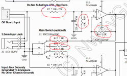
Look at the diagram here. Its vital that I know what the value is of the resistors marked (not exactly, just whether they are correctly identified and fitted). Now you can not measure resistors accurately in circuit because of interactions with other components. So go off the colour code and confirm that they agree with the circuit.
As written, the circuit implies that R7 is either 100 or 274 ohms and R14 is a 10k.
The feedback network that determines the gain is R16 (a 1.5k) and whichever resistor (either R17 or R19) is switched into circuit. According to the circuit that is either a 1k or a 274 ohm.
Now we can test the gain by applying a known voltage to the input and that voltage can be DC. So if you take a 1.5 volt battery and connect the negative terminal to ground and the positive terminal to the input (that's pin 1 of P1) and measure the DC voltage at the opamp output (that's pin 7) we can see if the stage is amplifying correctly.
Lets assume R17 (a 1k) is switched into circuit. The gain is equal to (R16+R17)/R17. So that is (1500 +1000) divided by 1000 which is 2.5
(so that is why its important to know the values of the resistors)
So if you apply 1.5 volts to the input you should see 3.75 volts on pin 7. If you measure the input voltage when the battery is connected and do the calculation it should be almost exact. So if you measure 1.56 volts on the input, you should see 3.9 volts on the opamp output.
If you now switch the other resistor in (lets say its the 274 ohm as drawn) then you would see 6.47 volts on the output pin (assuming the input was say 1.56 volts).
If you reverse the battery polarity then the opamp output will reverse to, and become a negative voltage.
That tests the first stage.
The second stage (U3) is just a buffer but we can test that too. If you link out C13 the stage is then DC coupled. If you turn the volume up to full and measure the voltage at the headphone output (you can measure on R10 or R11 for ease) then you should see a voltage that is the same as in the above tests. Turning the volume down should reduce that voltage smoothly to zero.
Testing that way proves beyond doubt that the gain is/isn't correct.
) what is happening. I assume you haven't got any test gear beyond a DVM, so here is what we do... and this is uncharted territory on the 02. (And unplug the headphones for doing this)Its not complicated, and it takes longer to read this than to do the test
As both channels are the same you need only do this on one channel. Also, there won't be a problem with U1, opamps don't give faults like low or wrong gain
But we'll try and prove it all. Look at the diagram here. Its vital that I know what the value is of the resistors marked (not exactly, just whether they are correctly identified and fitted). Now you can not measure resistors accurately in circuit because of interactions with other components. So go off the colour code and confirm that they agree with the circuit.
As written, the circuit implies that R7 is either 100 or 274 ohms and R14 is a 10k.
The feedback network that determines the gain is R16 (a 1.5k) and whichever resistor (either R17 or R19) is switched into circuit. According to the circuit that is either a 1k or a 274 ohm.
Now we can test the gain by applying a known voltage to the input and that voltage can be DC. So if you take a 1.5 volt battery and connect the negative terminal to ground and the positive terminal to the input (that's pin 1 of P1) and measure the DC voltage at the opamp output (that's pin 7) we can see if the stage is amplifying correctly.
Lets assume R17 (a 1k) is switched into circuit. The gain is equal to (R16+R17)/R17. So that is (1500 +1000) divided by 1000 which is 2.5
(so that is why its important to know the values of the resistors)
So if you apply 1.5 volts to the input you should see 3.75 volts on pin 7. If you measure the input voltage when the battery is connected and do the calculation it should be almost exact. So if you measure 1.56 volts on the input, you should see 3.9 volts on the opamp output.
If you now switch the other resistor in (lets say its the 274 ohm as drawn) then you would see 6.47 volts on the output pin (assuming the input was say 1.56 volts).
If you reverse the battery polarity then the opamp output will reverse to, and become a negative voltage.
That tests the first stage.
The second stage (U3) is just a buffer but we can test that too. If you link out C13 the stage is then DC coupled. If you turn the volume up to full and measure the voltage at the headphone output (you can measure on R10 or R11 for ease) then you should see a voltage that is the same as in the above tests. Turning the volume down should reduce that voltage smoothly to zero.
Testing that way proves beyond doubt that the gain is/isn't correct.
Attachments
- Home
- Amplifiers
- Headphone Systems
- The Objective2 (O2) Headphone Amp DIY Project