I found the problem. Stupid me had put the op amp for U1 in the socket of U2. I measured the voltages on the U1 socket and nothing exceeds the voltages that are meant for U1. I put in the correct place and measured everything all over again - all the voltages were the correct ones within a margin of error (0.01V which is most likely due to my cheapish DMM. I finished the build and the amp is now working. I need to put it in the case and I'll be done.Is Q1 bust... not if everything else is OK
Do you have +12 volts on pin 8 of U1 ? If not then measure the voltages on Q1. The gate should be pulled "low" toward -12 volts to turn it on.
Thanks!The two pins on the U6 regulator (nearest the filter caps - numbers 1 and 2 on the reg = input and ground?) had a solder bridge hence a dead short. Looking at the schematic, I checked the D4 diode for damage and found it was kaput (it was short circuited) so my next step is to replace that.
D4 would be the only casualty, other than possibly a PC trace. Since you shorted the U6 input to ground you protected the two filter caps (C3, C5) since the short resulted in zero volts across them. Once your remove D4, measure ohms on your meter between the middle pin of U6 and the side of D4's pads without the band. Should be nearly zero ohms if no PC board traces have fused. If they have you can just use some hookup wire to patch the trace. There is a trace on top of the PC board from the middle pin of U6 to C5, then it goes under the board from C5 to C3 and then D4.
Last edited:
Nothing else will be damaged in all probability.
D4 failed because of overload, the print depending on how thick it is may have suffered (gone open circuit) if the current flow was very large and its conceivable that J1 may have suffered (contacts may not be rated for that kind of current flow... all unlikely. No other components will have been damaged with a short between pins 1 and 2.
D4 failed because of overload, the print depending on how thick it is may have suffered (gone open circuit) if the current flow was very large and its conceivable that J1 may have suffered (contacts may not be rated for that kind of current flow... all unlikely. No other components will have been damaged with a short between pins 1 and 2.
I found the problem. Stupid me had put the op amp for U1 in the socket of U2. I measured the voltages on the U1 socket and nothing exceeds the voltages that are meant for U1. I put in the correct place and measured everything all over again - all the voltages were the correct ones within a margin of error (0.01V which is most likely due to my cheapish DMM. I finished the build and the amp is now working. I need to put it in the case and I'll be done.
That's good
Thanks for your replies.
I already replaced the diode IN4002 with another (a IN4001 - all I had) and there doesn't appear to be any burnt traces, but I've still got problems...
After replacing the IN4002 diode I connected the power supply but this time with a 40W bulb in series with the transformer, then switched it on and measured the supply voltage at the battery terminals as per the instructions (U2 not inserted).
The reading was 31vdc not the 24vdc it should have been. Also, the U6 reg was getting hot so I quickly turned off the power supply.
So, even with the solder bridge removed, I've still got problems with U6 getting hot (presumably by excess current or another short?) and the excessive voltage at the battery and that's with the 40W bulb in the cct - I wonder what would have happened if it wasn't there - more smoke?
One other test I've done (but without U2 inserted) is measure the DC voltages at D3 and D4 as described in "Check the raw DC Voltages" in the Blog.
It's getting late here but I think I did it correctly with really weird readings of D3 @ 41.75v and D4 @ 0.51v!! Both of these readings were to ground at the battery -ve terminal.
I'm confused - any suggestions? Perhaps the regulator is faulty; can I test it while in place?
I already replaced the diode IN4002 with another (a IN4001 - all I had) and there doesn't appear to be any burnt traces, but I've still got problems...
After replacing the IN4002 diode I connected the power supply but this time with a 40W bulb in series with the transformer, then switched it on and measured the supply voltage at the battery terminals as per the instructions (U2 not inserted).
The reading was 31vdc not the 24vdc it should have been. Also, the U6 reg was getting hot
so I quickly turned off the power supply. So, even with the solder bridge removed, I've still got problems with U6 getting hot (presumably by excess current or another short?) and the excessive voltage at the battery and that's with the 40W bulb in the cct - I wonder what would have happened if it wasn't there - more smoke?
One other test I've done (but without U2 inserted) is measure the DC voltages at D3 and D4 as described in "Check the raw DC Voltages" in the Blog.
It's getting late here but I think I did it correctly with really weird readings of D3 @ 41.75v and D4 @ 0.51v!! Both of these readings were to ground at the battery -ve terminal.
I'm confused - any suggestions? Perhaps the regulator is faulty; can I test it while in place?
D4 would be the only casualty, other than possibly a PC trace. Since you shorted the U6 input to ground you protected the two filter caps (C3, C5) since the short resulted in zero volts across them. Once your remove D4, measure ohms on your meter between the middle pin of U6 and the side of D4's pads without the band. Should be nearly zero ohms if no PC board traces have fused. If they have you can just use some hookup wire to patch the trace. There is a trace on top of the PC board from the middle pin of U6 to C5, then it goes under the board from C5 to C3 and then D4.
Nothing else will be damaged in all probability.
D4 failed because of overload, the print depending on how thick it is may have suffered (gone open circuit) if the current flow was very large and its conceivable that J1 may have suffered (contacts may not be rated for that kind of current flow... all unlikely. No other components will have been damaged with a short between pins 1 and 2.
Start at the beginning and measure and record these voltages. Firstly I would remove all the opamps U1 to U4
With your meter on DC volts and the black lead on ground,
1) What is the voltage on the striped end of D3 ?
2) What is the voltage on the NON striped end of D4
3) What is the voltage on the NON striped end of D1
4) What is the voltage on the striped end of D5
If anything gets hot or smokes with the opamps out then there is a fundamental problem at the front end.
Ah, damn it! Now I'm having issues with the grounding of the RCAs and it's really annoying. When I turn up the volume I can hear a loud (especially at high gain) and distinctive high pitched sound. t's similar to buzzing but its not a constant sound although I think there is some kind of a pattern in it. This happens every time I connect the amplifier using the RCA jacks to another device. I tried all different combinations of connecting the ground to the RCA but none of them solves the problem. First I had the two grounding rings connected to each other and soldered a single ground wire to them with the two RCAs and the rings touching the panel directly. Then I tried having again a single wire to both rings but this time with one RCA isolated from the panel using the plastic ring. I tried having both RCAs isolated again with the two rings touching. I tried running two separate ground wires with the RCAs touching the panel. Nope, still doesn't solve the problem. I've cut both traces on J2 and I'm soldering the ground as per NwAvGuy's guide for connecting an ODAC to the amplifier. If I disconnect the RCAs from the external device (a DAC) and touch them with my fingers I can hear a very loud buzzing sound. I've wasted over 3 hours trying to find the problem but I can't.. Any ideas?
P.S. I've sanded the area around the RCA holes even though the panels don't have any paint on them as they are brushed steel.
P.S. I've sanded the area around the RCA holes even though the panels don't have any paint on them as they are brushed steel.
Start at the beginning and measure and record these voltages. Firstly I would remove all the opamps U1 to U4
Thanks; Aside from measuring the resistances when U2 was in, all the opamps have been removed during testing and the switch S1 has been off.
Below are the readings across the diodes
With your meter on DC volts and the black lead on ground,
1) What is the voltage on the striped end of D3 ?
41.3v
2) What is the voltage on the NON striped end of D4
1.5v
3) What is the voltage on the NON striped end of D1
30.9v
4) What is the voltage on the striped end of D5
1.7v
If anything gets hot or smokes with the opamps out then there is a fundamental problem at the front end.
I agree
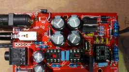
Here is a photo of the board if you can see anything obvious (Replacement diode for D4 is temporary).
Attachments
Something is seriously amiss here. If you really have 41 volts DC on D3 then that points to the input voltage from your adapter being sky high.
Firstly I would suggest you measure on AC VOLTS the voltage from ground to the Non striped end of D3 (the AC input to the board) What have you got ?
And another thought, is your adapter putting out AC ? which it should and not DC which it should not.
Firstly I would suggest you measure on AC VOLTS the voltage from ground to the Non striped end of D3 (the AC input to the board) What have you got ?
And another thought, is your adapter putting out AC ? which it should and not DC which it should not.
Something is seriously amiss here. If you really have 41 volts DC on D3 then that points to the input voltage from your adapter being sky high.
Firstly I would suggest you measure on AC VOLTS the voltage from ground to the Non striped end of D3 (the AC input to the board) What have you got ?
43.7vac
And another thought, is your adapter putting out AC ? which it should and not DC which it should not.
I'm using a multi-tapped transformer on the 0v and 15v winding.
I'll be back in a little while... also check your meter for accuracy... something doesn't add up here. 41 volts should have the caps going pop too unless they are rated at 63 volt. Try your meter across a battery or something to confirm its OK.
Checked the meter against other dc and ac sources and it's working OK. Something is definitely weird - with the power plug (to the board) out I'm getting 16.3vac across the plug contacts - how I'm getting 43.7vac at D3 above I don't know.
Maybe the transformer windng got damaged with the initial dead short and is failing under load? I'm going to look for a different transformer and try that.
I'm just trying to cover all bases with this...
If the tranny really is around 16 volts AC and you measure 40 odd volts AC when its connected to the board then the first thing I think of is that the print or socket is open circuit and the meter is reading "stray" voltage. The fact that nothing exploded also backs something like that up. Why not just hard wire the tranny to the board temporarily and test it that way. Has the ground connection become open between the reservoir caps and the socket ?
If the tranny really is around 16 volts AC and you measure 40 odd volts AC when its connected to the board then the first thing I think of is that the print or socket is open circuit and the meter is reading "stray" voltage. The fact that nothing exploded also backs something like that up. Why not just hard wire the tranny to the board temporarily and test it that way. Has the ground connection become open between the reservoir caps and the socket ?
Mooly, as you seem to be pretty knowledgeable on the O2 can you please take a look at my problem that's on the previous page. Thanks!
Yea, how come I've ended up doing all this troubleshooting... where's the designer got too I wouldn't say I was knowledgeable on the O2 particularly, I'd never seen one until just a few weeks back... but the circuitry is all easy to figure out... but grounding issues aren't I'm afraid.
You need to pin down what is happening. Does your O2 have batteries fitted ? Can you run it on a couple to see if the buzz is only present when mains powered. A high pitched (depends how high is high ?) isn't necessarily mains related. The AC input to the O2 should just be a floating AC supply and have no connection to ground. Its normal to get a very high buzz touching "open" inputs.
I'm just trying to cover all bases with this...
If the tranny really is around 16 volts AC and you measure 40 odd volts AC when its connected to the board then the first thing I think of is that the print or socket is open circuit and the meter is reading "stray" voltage. The fact that nothing exploded also backs something like that up. Why not just hard wire the tranny to the board temporarily and test it that way. Has the ground connection become open between the reservoir caps and the socket ?
Mooly, thanks. But..I'm an idiot
. I've rechecked everything and realised for the readings I gave you before I was using the -ve of BT2 as ground 
Using the correct BT2 +ve as ground now gives me:
1) What is the voltage on the striped end of D3 ?
22.8v
2) What is the voltage on the NON striped end of D4
20.8v
3) What is the voltage on the NON striped end of D1
11.9v
4) What is the voltage on the striped end of D5
20.4v
"For the reading for AC VOLTS the voltage from ground to the Non striped end of D3 (the AC input to the board) What have you got ?"
For this reading it's now 16.1vac at D3 it's 16.2vac at D4 (at the striped end.)
I've checked these readings three times. They make more sense - but my apologies for leading you up the garden path with my mistake.
I've still got the problem with U6 getting hot and the supply voltage at the battery (read across the + terminal of BT1 and the – terminal of BT2) at 32.5vdc.
Marcus... no problem.
Your readings,
1) Plus 22.8v is correct. Its the AC voltage times 1.414.
2) Should be Minus 22 volts ish, tracking the plus 22 volts. It might be a bit low because of a fault drawing current on that rail. If its minus 20 its OK.
3) 11.9 is spot on and within spec.
4) Again, is that minus 20 volts ? If it is then the regulator U6 is faulty or incorrectly fitted. If it really is plus 20 volts then you have a problem with a failed component somewhere shorting the plus rail to the minus rail.
Make sure all the opamps are removed for these tests... and they could well have suffered if they were installed when you had the earlier problem with the diode.
If U6 is getting hot and the opamps are removed then that again points to U6 being faulty.
S1 isolates all the circuitry from the power supply. With it off you should have no other contributing factors. The plus 12 volt rail is correct, the negative rail should mirror it at -12 volts.
no problem.Your readings,
1) Plus 22.8v is correct. Its the AC voltage times 1.414.
2) Should be Minus 22 volts ish, tracking the plus 22 volts. It might be a bit low because of a fault drawing current on that rail. If its minus 20 its OK.
3) 11.9 is spot on and within spec.
4) Again, is that minus 20 volts ? If it is then the regulator U6 is faulty or incorrectly fitted. If it really is plus 20 volts then you have a problem with a failed component somewhere shorting the plus rail to the minus rail.
Make sure all the opamps are removed for these tests... and they could well have suffered if they were installed when you had the earlier problem with the diode.
If U6 is getting hot and the opamps are removed then that again points to U6 being faulty.
S1 isolates all the circuitry from the power supply. With it off you should have no other contributing factors. The plus 12 volt rail is correct, the negative rail should mirror it at -12 volts.
It doesn't have batteries but I can install the terminals and try it with batteries. Can you tell me how the ground for the RCA jacks should be set up so I can rule that one out at least?
I'll have to leave it for tonight.
The RCA grounds should just go to the main ground on the PCB. It sounds like you have something else going on here, yes grounding is important but as this is all low power and low current circuitry the effects even of a "wrong" ground point should be minimal.
For a moment there I started thinking what does he mean by tonight.. it's already night here Don't worry, it's nothing urgent. That is quite weird, though.. One thing I noticed was that if I had no ground connected to the RCA plugs the amp would turn itself off as soon as I plugged in the headphones. Is this some kind of a protection design feature?
Don't worry, it's nothing urgent. That is quite weird, though.. One thing I noticed was that if I had no ground connected to the RCA plugs the amp would turn itself off as soon as I plugged in the headphones. Is this some kind of a protection design feature?For a moment there I started thinking what does he mean by tonight.. it's already night here
Its more night for you than for me, and in the morning it will be morning for you when its still night for me
Goodnight !- Home
- Amplifiers
- Headphone Systems
- The Objective2 (O2) Headphone Amp DIY Project