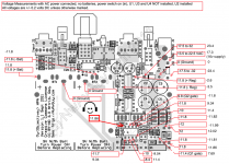
Ok, I believe I am in need of some help. I went to take some voltage measurements of my O2 this am (was working perfectly). And when I touched pin 8 on U2 to measure the voltage, I got a spark, followed by the LED turning off. I looked down and noticed that my DMM had the leads in the incorrect positions (not sure if that was what caused the spark or not). I took out U1, U3 and U4, then got the following measurements. Thinking I fried the IC, I went out and got an LM393 (shows as the same chip as the LM2903 in the datasheet), hooked it up, and got the same exact measurements.
A couple of odd things to note the measurements from the sockets on U3 sometimes show 11.8 and -11.8 as it should (random, can't figure out what makes it correct). R5 when the power switch is off measures 235k and when the power switch is on measures 88k.
Any suggestions?")
Thanks in advance!
Erik
A couple of odd things to note the measurements from the sockets on U3 sometimes show 11.8 and -11.8 as it should (random, can't figure out what makes it correct). R5 when the power switch is off measures 235k and when the power switch is on measures 88k.
Any suggestions?
Thanks in advance!
Erik
Attachments
I looked down and noticed that my DMM had the leads in the incorrect positions (not sure if that was what caused the spark or not).
Those other lead positions on most DMMs are for current measurements. They result in the meter essentially being a dead short between the two leads. You most likely shorted out your power supply. The LED is directly across the power supply rails, which also sort of points to no juice any more. It only goes out if one or both power supplies are missing going into the mosfets.
With the AC adaptor plugged in and the batteries out, take a DC voltage reading from ground (metal shell of the gain switch) to the non-banded side of D1 (that is your +12V supply) and to the banded side of D5 (your -12Vdc supply) and see what you get.
If you had one meter lead on ground and touched pin 8 with the other, I'll take guess that you killed D1. If you were measuring pin 4 to pin 8 across the rails then D1 and D5 may both be open. Pin 8 is the positive power supply. U5, the positive voltage regulator, has some short circuit protection which leaves D1 as the weak link between the regulator and the short caused by the meter leads. It is also possible that you blew (fused) the positive PC rail circuit board trace in one or more spots. Take a good look at the traces on both sides of the board with a magnifying glass. Also, I'm assuming you were running on AC power when you touched the meter lead. If you were running on batteries instead then I'll guess that D2 is what's toasted.
Last edited:
Those other lead positions on most DMMs are for current measurements. They result in the meter essentially being a dead short between the two leads. You most likely shorted out your power supply. The LED is directly across the power supply rails, which also sort of points to no juice any more. It only goes out if one or both power supplies are missing going into the mosfets.
With the AC adaptor plugged in and the batteries out, take a DC voltage reading from ground (metal shell of the gain switch) to the non-banded side of D1 (that is your +12V supply) and to the banded side of D5 (your -12Vdc supply) and see what you get.
If you had one meter lead on ground and touched pin 8 with the other, I'll take guess that you killed D1. If you were measuring pin 4 to pin 8 across the rails then D1 and D5 may both be open. Pin 8 is the positive power supply. U5, the positive voltage regulator, has some short circuit protection which leaves D1 as the weak link between the regulator and the short caused by the meter leads. It is also possible that you blew (fused) the positive PC rail circuit board trace. Take a good look at the traces on both sides of the board with a magnifying glass. Also, I'm assuming you were running on AC power when you touched the meter lead. If you were running on batteries instead then I'll guess that D2 is what's toasted.
I also meant to say that the attached image above has all the measurements I took afterwards. The reference measurements are in the red boxes, and my measurements are on the outside (except for the one in the ugly red box in the middle, that is mine, and where wasn't a reference measurement). Also, I need to correct myself, I touched pin 5, I was confused on which way the pin numbering worked.
I'll take a close look at the board shortly.
Thanks
Erik
Last edited:
Erik - I forgot about your voltage diagram. Good work on that.
You shorted out your LED and it is open. That is why you are getting +11.4Vdc on pin 5 now. With the LED gone the resistor R6 will pull that pin up to the positive power rail. Your power supplies are OK, as are diodes D1, D2, D5, and D6.
Since you were planning on getting rid of your LED anyway everything works out. Replace it with that 1.8V zener (polarity rotated) and you are back in business. If you are ordering parts it would be a good idea to get another U2 just in case.
Good work on that. You shorted out your LED and it is open. That is why you are getting +11.4Vdc on pin 5 now. With the LED gone the resistor R6 will pull that pin up to the positive power rail. Your power supplies are OK, as are diodes D1, D2, D5, and D6.
Since you were planning on getting rid of your LED anyway everything works out. Replace it with that 1.8V zener (polarity rotated) and you are back in business. If you are ordering parts it would be a good idea to get another U2 just in case.
Last edited:
Erik - hey that is good news! You are probably one of the first to replace the O2's LED with a zener.
If anyone else needs to to do the same the zener is a 1N4614:
1N4614 Central Semiconductor | Mouser
Mouser #610-1N4614. That is a 1/4watt zener with a test voltage of just 250uA. The O2's LED circuit is running 22V/40.2k = 540uA through the LED, close enough to that zener's test current to come very close to the rated 1.8Vdc, same as the LED. Just remember to rotate the polarity of the zener from that of the LED.
Here is an interesting piece from Happy 2013! | JDS Labs Blog
jseaber Post author
January 14, 2013 at 7:45 am
NwAvGuy is definitely MIA. Our good friend George Boudreau (ODAC board designer) sent him a courier letter in early December. The letter was signed for, but no reply. He must have his reasons.
jseaber Post author
January 23, 2013 at 8:32 pm
@Chris: My feelings are the same. Interestingly, bursts of creativity and subsequent withdraw behavior are common amongst brilliant artists and designers.
I spoke with George Boudreau again last Monday. George claims to be one of two people in the DIY audio community who have NwAvGuy’s mailing address, and even George was given only his three initials (not even a first name!). George was asked to keep NwAvGuy’s initials and address strictly private, and he’s not even sure whether the address is a home or office.
More interesting was George’s story of ODAC development. He said that design of ODAC began after NwAvGuy had begun designing ODA. They exchanged emails rapidly for a few weeks. NwAvGuy suddenly stopped writing, disappeared for over three months straight without an explanation, and so George assumed ODAC and ODA were both dead projects! George commented that, “something serious” had happened which caused NwAvGuy to set his DIY contributions on the shelf (a family death, he believes).
Thus, it’s not absolutely certain that NwAvGuy will be gone forever. I’m sure he has his reasons.
Unfortunately NwAvGuy is MIA but he did inspired countless others to go down the Objective path!
Any self respecting headphone amp manufacturing company that is worth its salt will have its product compared (w.r.t. specs. & pricing) to O2 from now on before making any esoteric claims.
jseaber Post author
January 14, 2013 at 7:45 am
NwAvGuy is definitely MIA. Our good friend George Boudreau (ODAC board designer) sent him a courier letter in early December. The letter was signed for, but no reply. He must have his reasons.
jseaber Post author
January 23, 2013 at 8:32 pm
@Chris: My feelings are the same. Interestingly, bursts of creativity and subsequent withdraw behavior are common amongst brilliant artists and designers.
I spoke with George Boudreau again last Monday. George claims to be one of two people in the DIY audio community who have NwAvGuy’s mailing address, and even George was given only his three initials (not even a first name!). George was asked to keep NwAvGuy’s initials and address strictly private, and he’s not even sure whether the address is a home or office.
More interesting was George’s story of ODAC development. He said that design of ODAC began after NwAvGuy had begun designing ODA. They exchanged emails rapidly for a few weeks. NwAvGuy suddenly stopped writing, disappeared for over three months straight without an explanation, and so George assumed ODAC and ODA were both dead projects! George commented that, “something serious” had happened which caused NwAvGuy to set his DIY contributions on the shelf (a family death, he believes).
Thus, it’s not absolutely certain that NwAvGuy will be gone forever. I’m sure he has his reasons.
Unfortunately NwAvGuy is MIA but he did inspired countless others to go down the Objective path!
Any self respecting headphone amp manufacturing company that is worth its salt will have its product compared (w.r.t. specs. & pricing) to O2 from now on before making any esoteric claims.
Last edited:
NwAvGuy
I have not heard from NwAvGuy since late July of 2013. As John wrote I did send a courier envelope to him but there was no reply. Possibly he is on the beach in California or picking oranges in Florida. His choice, his privacy.
It was fun designing the ODAC board and it took 5 kicks at the can before we were satisfied. NwAvGuy burned a lot of midnight oil fussing over the parts choices for the ES9023 which is why such a 'simple' board meets the manufacturers specs.
It would be nice if strolled back some day if only to say 'Hi'
regards,
George Boudreau
I have a friend that would like one of these and I would be happy to build it for him. The only thing I cannot help him with is the power adapter. He is from Australia and needs a 240v with the appropriate plug. Could someone be so kind as to point me in the right direction?
Thanks!!
Thanks!!
billyk said:He is from Australia and needs a 240v with the appropriate plug. Could someone be so kind as to point me in the right direction?
simpliest solution is to have a female AC socket on the chassis - then he can easily attach a power cable. There only 2 common types of sockets, so should be no problem.
I think billyk is looking for a source of 15VAC plug packs with an Australian plug. (Whether the other end is a 5.5/2.5 or 5.5/2.1mm is probably irrelevant.)
These are actually hard to find, even more so since the sale of inefficient (read: non-SMPS, with transformers at mains frequency) DC supplies have been banned in many countries (Australia included, as far as I know).
I had similar problems looking for an appropriate plug pack since I did not want to do mains wiring myself, and it took me an hour or so to find a supplier of AC plug packs where I live. I don't really have a clue where to start looking for stuff in AU, but a quick search on ebay says it's not totally hopeless: 12VAC 500mA AC Power Supply Adaptor | eBay (No endorsement of product or seller.)
DIY. A box, transformer, and a couple of interconnects may be easier to find. For less money....looking for a source of 15VAC plug packs...
...These are actually hard to find,...
And does anybody have any I idea why I get a bit more volume on the right channel, especially lower sounds. I've got panel mounted rca- and 1/4" jacks.
All vol. pots have slight channel imbalance problem at lower end(around 8' o clock or less pos.) but should not have any problem after 9 o' clock pos. & onwards. If it still gives channel imbalance at all vol. levels then recheck all solder points or else vol. pot is bad.
Also use low gain settings (2X-3X) for max. vol. control sweep.
- Home
- Amplifiers
- Headphone Systems
- The Objective2 (O2) Headphone Amp DIY Project