Can anyone tell me where I can find detailed assembly instruction for the O2, sort of a walk-through guide, I searched Google but didn't find any. Is there something around here that resembles that?
Thanks for your help
http://www.diyaudio.com/forums/headphone-systems/217086-building-o2-headphone-amp.html
gain switching/resistors questions
Hi guys- I have almost got my O2 put together.
I am confused about the configuration of the gain switching resistors.
My build is for an AC only desk unit. I decided not to buy a gain switch. My thinking was to have a fixed gain and to use the SIP pin sockets for the gain resistors.
From the nwavguy resources page: "NO GAIN SWITCH: You can jumper around the gain switch and leave out two of the gain resistors if you want only a fixed gain amp. But testing shows the gain switch does not hurt the performance and it adds a lot of versatility for future sources and headphones. There are jumper marks on the PC board along the sides of S2 showing where to install jumpers if you leave the switch out."
Well, I guess I'm not interpreting that correctly. I thought he means to place two jumpers on the board where marked and then I can use just two resistors for a fixed gain.
However, regardless of what I do, I get 1X gain.
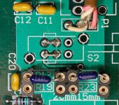
Attached is a photo of my board.
Initially, I soldered in jumpers as shown in the photo. When I found that doesn't work, I cut them- no change. I even shorted in the opposite driection (vertical instead of horizontal, looking at the photo)- no change.
What am I dong wrong?
Thanks,
Keith Ostertag
Hi guys- I have almost got my O2 put together.
I am confused about the configuration of the gain switching resistors.
My build is for an AC only desk unit. I decided not to buy a gain switch. My thinking was to have a fixed gain and to use the SIP pin sockets for the gain resistors.
From the nwavguy resources page: "NO GAIN SWITCH: You can jumper around the gain switch and leave out two of the gain resistors if you want only a fixed gain amp. But testing shows the gain switch does not hurt the performance and it adds a lot of versatility for future sources and headphones. There are jumper marks on the PC board along the sides of S2 showing where to install jumpers if you leave the switch out."
Well, I guess I'm not interpreting that correctly. I thought he means to place two jumpers on the board where marked and then I can use just two resistors for a fixed gain.
However, regardless of what I do, I get 1X gain.
Attached is a photo of my board.
Initially, I soldered in jumpers as shown in the photo. When I found that doesn't work, I cut them- no change. I even shorted in the opposite driection (vertical instead of horizontal, looking at the photo)- no change.
What am I dong wrong?
Thanks,
Keith Ostertag
Attachments
I thought he means to place two jumpers on the board where marked and then I can use just two resistors for a fixed gain
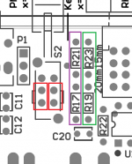
You almost had it! Wrong two resistors. The resistors go in the R19 and R23 sockets, with the R17 and R21 sockets where you have the resistors now left blank. So just move your resistors to the other two sockets and it should work.
I've attached a diagram below. Red are the switch jumpers, which look OK on yours. Green is where the gain resistors should go, and purple are the holes or sockets that are left blank.
Attachments
Thanks ADGR!
Yea, I spent a good hour figuring this out before I got your message... it's not obvious (at least to me) from the PCB markings or the text. Also, I'm not particularly good at following PCB traces, especially double-sided ones...
Turns out, after all that, I've decided to leave the gain resistors out- 1X seems to work fine for me. Easy to install them in the future- that's why I used those SIP sockets.
BTW- how to put images inline for these board posts? I'd like to post some photos of my completed project.
Thanks,
Keith Ostertag
BTW- how to put images inline for these board posts? I'd like to post some photos of my completed project.
I've never been able to figure out the magic to get inline images to work on DIYA. I would be curious myself.
") I've just used the attachments so far.
I've just used the attachments so far.O2 project report- rack mount unit
OK, here's what I've put together.
For my O2, I wanted to put it in a rack mount unit, and provide an extra set of paralleled inputs as a "pass through". This so I can put it in my rack unit we use for our entertainment center- one input comes from the DVD source, the other goes to an EQ and the rest of the stereo system. This way my wife can use the headphones while we watch a movie, and I can turn the sound up as loud as I want without affecting her headphone volume. We had been using the "monitor output" on my Crown amp- not bad sound, but no separate volume control (I don't use a preamp with my system). Using this with a BeyerDynamic DT880 (250 ohms).
I have a fair amount of junkbox parts I wanted to use, and most of my work on this project was in fitting them. Populating the O2 board was trivial, other than my poor eyesight and a few mis-identified traces/routings.
I put in a switch to the headphone output: just a precaution to use when plugging in-and-out of the amp.
Here's a photo of the major parts:
http://www.strucktower.com/o2_sections.jpg
The rack unit was bought at a local yard sale for $5 last year. I just spray painted it and replaced the guts with the O2, drilling holes where needed for remote inputs, etc. I used a sheet of old copper-clad (PCB) board for the base.
Here's a photo of the inputs:
http://www.strucktower.com/o2_input_outside.jpg
http://www.strucktower.com/o2_input_inside.jpg
The power transformer I got for $1 at a hamfest a few years ago- puts out about 17VAC and comes with it's own little circuit board with line conditioning and fuse. I dropped this and broke the board- then the repair slipped after I had clamped it and walked away... oh well.
http://www.strucktower.com/o2_ps.jpg
I happened to have a dual section military grade 5-position switch, always wondered what I could do with it. So I decided to turn it into a 5-step attenuator for the volume control. I couldn't find much info on how to make one- all the info I saw gave db values but no resistor values- maybe I didn't look hard enough? Anyway, I decided we didn't need low volume, and I limited myself to resistors I had on-hand, and I assumed (maybe wrongly?) that I should keep total values across each to 10K. The values I came up with are (wiper in the middle):
5.7K + 4.5K
6.8K + 3.9K
7.6K + 2.5K
8.2K + 1.8K
9.4K + .9K
Even though I had no idea how these would work out, happily it turns out just fine. Though I am only using the O2 at 1X gain, there's more than enough volume, and in fact one change I might make is replace the lowest section to reduce the volume further.
I etched a quick and dirty PCB with two concentric circles for the wipers: here's a look at how it turned out:
http://www.strucktower.com/o2_vol_side.jpg
http://www.strucktower.com/o2_vol_rear.jpg
You can see I used twisted pair as cable for it.
One of the more dumb things about this build was how difficult it was to install my 1/4 phone jack for headphone output. It has a large diameter shaft- plus I needed space for an insulator. I didn't have a drill bit that big- 3/4 inch. So I had to punch through the rack unit's aluminum front plate- 3mm! Took a lot of effort and a long torque bar. Then, I spent hours fabricating an insulator to fit because the shaft was just barely long enough. Oh boy, was that a lesson in choosing standard components!
Here's a photo of the remote power connections. Sloppy job with those, sorry. Notice- for strain relief I use a strong fiber string, similar to what they use for parachutes.
http://www.strucktower.com/o2_power_connections.jpg
Here's a photo of the gain resistors- taken before I corrected their placement (thanks agdjr) and eventually just removed them.
http://www.strucktower.com/o2_gain_resistors.jpg
I used good quality shielded audio cables (made by Amp) that I salvaged from a vintage stereo years ago.
Here's the final product:
http://www.strucktower.com/o2_final.jpg
Due to the size of the box around the transformer the whole thing takes a little more than one unit height, but I room have for it. If I come by a full size single rack unit in the future I can swap it easily.
In the future I will try to put more emphasis on better soldering and aesthetics. My soldering skills are not bad- I just have trouble seeing that close. Also, the smallest tip I have is 1/8", not really small enough for this type work.
So, to leave you with something humorous, let me show you a classic example of a really bad soldering job:
http://www.strucktower.com/o2_mistake.jpg
Hey, at least I was able to find it!
I hope this post helps give ideas to someone, or at least makes some of you laugh.
If any of you want to comment, thanks. Especially re the attenuator.
A special thanks to Eric who took the time out to help me with a part.
Keith Ostertag
I had read somewhere that RS expected total O2 sales(kits/finished products) to be modestly in the region of couple of hundred or so. Does anybody have any idea of how many of O2s have actually been sold?(just out of curiosity).
My guesstimate is above 10,000 O2s .Maybe O2 builders/kits seller together can provide better data)
Hey, at-least RS(and his famous objective calculations) was way off the mark on this count
).My guesstimate is above 10,000 O2s
.Maybe O2 builders/kits seller together can provide better data)Hey, at-least RS(and his famous objective calculations) was way off the mark on this count
Last edited:
I had read somewhere that RS expected total O2 sales(kits/finished products) to be modestly in the region of couple of hundred or so. Does anybody have any idea of how many of O2s have actually been sold?(just out of curiosity
My guesstimate is above 10,000 O2s
Hey, at-least RS(and his famous objective calculations) was way off the mark on this count
I've heard of at least 10 O2s on a Swedish computer hardware forum I'm frequently visiting. So there's probably at least 20 or even more in Sweden I'd guess.
I think that ~10000 or more it a good estimation.
has anyone thought about using a bluetooth module like this for an input?
Bluetooth 2 1 EDR Audio Communication Module Wireless Music Stereo | eBay
some sites may have trubble with long urls, so here is tiny same link in tiny Bluetooth 2 1 EDR Audio Communication Module Wireless Music Stereo | eBay
I think it would be a great addon.
Bluetooth 2 1 EDR Audio Communication Module Wireless Music Stereo | eBay
some sites may have trubble with long urls, so here is tiny same link in tiny Bluetooth 2 1 EDR Audio Communication Module Wireless Music Stereo | eBay
I think it would be a great addon.
I have a weird issue with my o2. My setup includes an odac and pc for playing music. i have connected an extra 6.4mm output. the 6.4mm output works fine, no issues. but the regular on board 3.5mm output is always on, if pc is playing music, its coming through the 3.5mm output, it doesnt matter if O2 is on or Off, volume control has no impact, gain switch has no impact, volume and gain dont work even with the O2 on with 3.5mm port.... has anyone faced this issue.
i had lost a 220nf bypass cap which i am yet to solder, apart from that from the build perspective i am not aware of any issues.
i had lost a 220nf bypass cap which i am yet to solder, apart from that from the build perspective i am not aware of any issues.
it's not like buying the components in China would have been easy anyway.
perhaps you are not aware of SEG in Shenzhen?
FOUR buildings, 10 floors in one, 8 in another, 6 in the third, and 4 in the fourth building. Each floor pretty much choked with electronic products, electronic modules, electronic parts.
Perhaps well over 1,000 shops dealing in electronics.
If you can not source it there, you gotta be deaf, mute, and blind.
And I have a top tier sourcing agent there. And a hard-as-nails, meaner-than-a-junkyard-dog QA assistant [oddly enough she is a tall, slender, stylish, drop-dead attractive lady! ]
I suppose one profitable prototype a millionaire does not make
isn't Windows still a prototype?
I have a weird issue with my o2. My setup includes an odac and pc for playing music. i have connected an extra 6.4mm output. the 6.4mm output works fine, no issues. but the regular on board 3.5mm output is always on, if pc is playing music, its coming through the 3.5mm output, it doesnt matter if O2 is on or Off, volume control has no impact, gain switch has no impact, volume and gain dont work even with the O2 on with 3.5mm port.... has anyone faced this issue.
i had lost a 220nf bypass cap which i am yet to solder, apart from that from the build perspective i am not aware of any issues.
i had accidently connected the hp to the input port and basically was listening to odac output. I seriously need to put some effort and label the front panel.
What impact .... if one uses ordinary 220pF ceramic capacitor(C11,12,19,20) .....
Where angels fear to tread?
Pandora's box?
...............at the huge risk to my head or other body parts.........
there are raging bitter vehement debates on the sonic qualities of the various types of caps............
some [types of] caps are more stable
some have tighter/better tolerances
some can withstand higher voltages
some look nicer!
use what you will/can then try replacing..............and see if you tell the difference
- Home
- Amplifiers
- Headphone Systems
- The Objective2 (O2) Headphone Amp DIY Project