Anyone got any ideas for making an ODAC sized USB hole for the rear faceplate?
I successfully drilled holes for the frontplate. However, a drill is all I have so right now it seems like I'm going to have to drill a large, round hole for the ODAC usb port and then find some way of making a surround (perhaps with a glue gun). Any suggestions on making surrounds would be great also.
Hmm, I'd think about investing in some Needle Files, drill one hole and file out the shape needed... should take less than 20 minutes.
Hmm, I'd think about investing in some Needle Files, drill one hole and file out the shape needed... should take less than 20 minutes.
I used to do this and it works well.
just make sure that your needle file is perpendicular to the hole, then you will get a nice even surface, otherwise your hole will get bigger and come out all crooked
in the beginning work slow and get a feel for the technique.. i usually use a marker to mark off sections that is "high" (needs more filing) and then mark on the panel where to stop filing (edge of hole)
-joe
If Tandy in the UK is like Radio Shack in the US, they sell a "nibbler" tool meant to cleanly cut small squares of soft metal or plastic sheeting. To use the tool you just drill a small access hole for the tool and then you can create straight-edged cuts and openings easily.
My "nibbler" tool has saved the day on a number of DIY projects.
Here's a link to what I'm talking about:
GO! MOD Nibbler 29524 Metal Cutting Tool : General tools & tool kits | RadioShack.com
My "nibbler" tool has saved the day on a number of DIY projects.
Here's a link to what I'm talking about:
GO! MOD Nibbler 29524 Metal Cutting Tool : General tools & tool kits | RadioShack.com
Anyone got any ideas for making an ODAC sized USB hole for the rear faceplate?
I successfully drilled holes for the frontplate. However, a drill is all I have so right now it seems like I'm going to have to drill a large, round hole for the ODAC usb port and then find some way of making a surround (perhaps with a glue gun). Any suggestions on making surrounds would be great also.
Can anyone point me towards a Front Plate stencil so I can make my custom desktop version O2 amp? I want to have the RCA red/white plugs as well as the 1/4" adapter. Does the 1/4" adapter go on the front and the RCA plugs in the back? Also how do the RCA plugs attach as well as the 1/4" adapter. Thank you!
Can anyone point me towards a Front Plate stencil so I can make my custom desktop version O2 amp? I want to have the RCA red/white plugs as well as the 1/4" adapter. Does the 1/4" adapter go on the front and the RCA plugs in the back? Also how do the RCA plugs attach as well as the 1/4" adapter. Thank you!
depending on the jacks you use, i think there was a groupbuy on the b3 panels, they should have pictures or template there
the rca would go to the back and be wired into the input header
the headphone jack would go in the front and be wired to the output header
you would probably want to relocate the volume control to the front as well.
-joe
hi,
I suspect mosfet Q2 is out
i found an IRF 630 from a supplier near me,but the VGS is +-20v,where i can measure vgs?
Will it works or burns or only works with battery(2X9)
thanks for help
Vgs(max) of 20Vdc for the mosfets won't work (for very long, anyway). The power supply rails when running on AC are +/-12Vdc, so there is 24Vdc rail to rail, or more like 23Vdc after voltage drops across the schottky diodes and comparator chip output. The " 9v" NiMH batteries charge up to around 10.5Vdc, as I recall. That results in 21Vdc rail to rail when running on batteires, or right at 20Vdc after the various voltage drops.
So... you should get a mosfet with a Vgs(max) of at least 25Vdc. All the alternate mosfets RocketScientist lists in the BOM have Vgs(max) = 25Vdc.
Good luck!
Last edited:
Found some low ppm (<50ppm) 0603 surface mount resistors in drawer. Decided to replace R14, 20, 16, 22, 12, 13. Also add bass boast R16 and 22 with 0.1uF film cap as agdr suggested in the other post.
After done, hock it up to my BII DAC, I listen to it for 3hr. All i can say is, It is very nice to my ear, I like it a lot.
Did know how to upload picture with iPad. Maybe later will upload.
After done, hock it up to my BII DAC, I listen to it for 3hr. All i can say is, It is very nice to my ear, I like it a lot.
Did know how to upload picture with iPad. Maybe later will upload.
Found some low ppm (<50ppm) 0603 surface mount resistors in drawer. Decided to replace R14, 20, 16, 22, 12, 13. Also add bass boast R16 and 22 with 0.1uF film cap as agdr suggested in the other post.
After done, hock it up to my BII DAC, I listen to it for 3hr. All i can say is, It is very nice to my ear, I like it a lot.
Did know how to upload picture with iPad. Maybe later will upload.
Here is the picture, the picture is not so good as I am using mobile phone to capture it. All old resistors are removed and new SMD resistors are mount underside of the board as it is easier to work with.

Here is the picture
Hey that is pretty slick!
") You found a way to use the (bigger than ceramic) film caps for the boost mod by sticking them on the bottom. I like the contrast there, the tiny SMD resistors and the huge 0.1uF film cap. That is what is needed electrically though. Looks like you are not going to use a switch on the boost mod (on all the time)? Another fellow has tried the boost mod and discovered the switch really doesn't fit anywhere in a B2-080 chasis. Have to go to B3. I just wired it all up to make sure it worked electrically, but hadn't tried to mount the switch in the box and got caught flat footed on that one.
You found a way to use the (bigger than ceramic) film caps for the boost mod by sticking them on the bottom. I like the contrast there, the tiny SMD resistors and the huge 0.1uF film cap. That is what is needed electrically though. Looks like you are not going to use a switch on the boost mod (on all the time)? Another fellow has tried the boost mod and discovered the switch really doesn't fit anywhere in a B2-080 chasis. Have to go to B3. I just wired it all up to make sure it worked electrically, but hadn't tried to mount the switch in the box and got caught flat footed on that one.Yup, it is on all the tim,. I need more bass all the timeHey that is pretty slick!
. and I also don't know where to mount the switch in my B2 case.Hi AGDR,many thanks for you reply,
By searching on the forum,i found a post of nwavguy who used 20V vgs mosfet with succes and one can add 15V zener in //to G/S
You understand i cannot order a 1,50€ mosfet and pay 20€ of shipping so i must find the part locally
In the meantime,i found the culprit it was not the mosfet but the comparator 2903!!,i replace it with an LM2903 and all works fine now for many hours
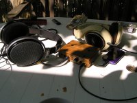
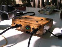
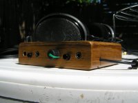
I'll post asap a photo of my box in... walnut
patrice
e
By searching on the forum,i found a post of nwavguy who used 20V vgs mosfet with succes and one can add 15V zener in //to G/S
You understand i cannot order a 1,50€ mosfet and pay 20€ of shipping so i must find the part locally
In the meantime,i found the culprit it was not the mosfet but the comparator 2903!!,i replace it with an LM2903 and all works fine now for many hours
I'll post asap a photo of my box in... walnut
patrice
e
Vgs(max) of 20Vdc for the mosfets won't work (for very long, anyway). The power supply rails when running on AC are +/-12Vdc, so there is 24Vdc rail to rail, or more like 23Vdc after voltage drops across the schottky diodes and comparator chip output. The " 9v" NiMH batteries charge up to around 10.5Vdc, as I recall. That results in 21Vdc rail to rail when running on batteires, or right at 20Vdc after the various voltage drops.
So... you should get a mosfet with a Vgs(max) of at least 25Vdc. All the alternate mosfets RocketScientist lists in the BOM have Vgs(max) = 25Vdc.
Good luck!
By searching on the forum,i found a post of nwavguy who used 20V vgs mosfet with succes and one can add 15V zener in //to G/S
Yep, a zener, or resistive divider, added on the gate circuit to reduce the voltage would also work.
That is good news you got it working!
Can anyone point me towards a Front Plate stencil so I can make my custom desktop version O2 amp? I want to have the RCA red/white plugs as well as the 1/4" adapter. Does the 1/4" adapter go on the front and the RCA plugs in the back? Also how do the RCA plugs attach as well as the 1/4" adapter. Thank you!
Be careful of JSChristian44. So far, he has taken members on Head-Fi.Org for $1,000+ in money and merchandise. Normally, he resides in Pennsylvania, but is apparently in Alaska for the summer.
Here is the picture, the picture is not so good as I am using mobile phone to capture it. All old resistors are removed and new SMD resistors are mount underside of the board as it is easier to work with. View attachment 283268
Nice work, coolhead! Inspired by your work, I make bass boost too, few days ago. With ordinary resistors. Now in my O2 gain switch work as bass boost switch too. Since I use gain 2 and unity, Gain 2 is with bass boost and in unity gain position bass boost practically does not work.
I have 3K in feedback and 3K+100nf in parallel.
b.t.w., coolhead, since you use SMD resistors, you can make physically shortest possible feedback loop. Just solder feedback resistor direct between opamp's pin 1 and 2, and between 6 and 7. Leave in old place only bass boost RC.
and voila!Hi AGDR,many thanks for you reply,
By searching on the forum,i found a post of nwavguy who used 20V vgs mosfet with succes and one can add 15V zener in //to G/S
You understand i cannot order a 1,50€ mosfet and pay 20€ of shipping so i must find the part locally
In the meantime,i found the culprit it was not the mosfet but the comparator 2903!!,i replace it with an LM2903 and all works fine now for many hours
I'll post asap a photo of my box in... walnut
patrice
e
Attachments
ODAC wiring...
Hi everyone, two quick reference pic's for those looking to wire their ODAC to the O2.
1. Odac lineout connects to P1 on the O2 board. P1.1 [square] = left, P1.2 = Gnd, P1.3 = right.
2. IIRC, with the input jack fitted you need to cut two traces on the reverse of the board.
Paul.
Hi everyone, two quick reference pic's for those looking to wire their ODAC to the O2.
1. Odac lineout connects to P1 on the O2 board. P1.1 [square] = left, P1.2 = Gnd, P1.3 = right.
2. IIRC, with the input jack fitted you need to cut two traces on the reverse of the board.
Paul.
Attachments
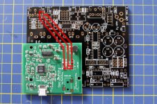
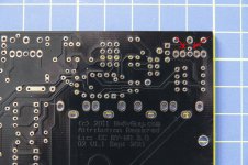
If you wire to P1 holes, the ODAC will always be connected to the amp input.
If you want the jack switch to function to select between external source (jack in),
or internal ODAC (no jack in), you cut the traces and then ODAC L & R connection
are pins 3 & 4 of the input jack socket on the underside of the O2 PCB.
In order to route the wires for L & R, I squeezed some 24g teflon insulated wire through
the PCB lead holes at P1 and under the board to solder to pins 3 & 4.
Last edited:
Hi Guys,
Sorry to be a little of topic but I'm running a charity raffle to win JDS gear including the O2 Headphone Amplifier and ODAC to help build schools in Kenya and Tanzania, details can be found on the raffle page:
Charity Giving - JDS LABS CHARITY RAFFLE PAGE
There's an article on JDS Labs:
JDS Labs
We're hoping to generate a little more interest because we don't have many entries at the moment so your participation would be gladly appreciated, also the odds of winning are good
- Home
- Amplifiers
- Headphone Systems
- The Objective2 (O2) Headphone Amp DIY Project